New Construction Above Ground Storage Tanks
OVERVIEW:
This technical bulletin addresses the design and installation of cathodic protection systems for new construction above ground storage tanks (ASTs). Cathodic protection (CP) is typically applied to all above ground storage tanks built on a ring wall foundation to protect the external tank bottom in contact with the soil/sand foundation. Smaller tanks built on concrete slab foundations typically do not have cathodic protection applied to them.
In many locations, cathodic protection is mandated by local regulations for tanks storing hydrocarbons or hazardous materials; however, even in the absence of such mandates, good engineering practice would generally dictate cathodic protection.
Summary/Conclusion:
MATCOR typically recommends the use of linear anodes in a concentric ring configuration as the most reliable system design for new construction above ground storage tanks, combining economy of material requirements with ease of installation.
Galvanic vs. Impressed Current
Historically, various configurations of galvanic anodes, including discreet anodes and ribbon type anodes, have been used to protect AST bottoms. Experience has shown that these systems do not provide the uniform current distribution necessary over the entire CP system design life and result in premature failure as the galvanic anodes consume. ASTs require significant current, which generally precludes the use of galvanic anodes. Almost all AST CP systems today are designed with impressed current systems to provide the current required over a long period of time.
Design Information:
The following information is required to develop a CP design for ASTs:
Tank Diameter
This is necessary to calculate the surface area to be protected.
Tank Bottom Coating
Typically tank bottoms are bare plate steel, but in some cases the plate steel may be coated on the bottom, which reduces the current required for cathodic protection. CP is still recommended for tanks with coated bottoms.
Current Density Required
Typical design current density requirements of 1 mA/ft2 (10 mA/m2) are sufficient to achieve NACE criteria for cathodic protection (see discussion on operating temperature).
Depth of Anode
The separation distance between the anode and the tank bottom affects current spread and anode spacing.
Sand/Soil Resistivity
This information is necessary to estimate overall system resistance necessary to properly size the rectifier voltage. In many cases, it may make sense to install the anode system and test the actual circuit resistance using a portable rectifier or car battery before committing to a specific rectifier size.
Tank Operating Temperature
Corrosion rates increase significantly with elevated temperature, necessitating more current. MATCOR uses the following temperature correction formula for its CP designs for heated tank bottoms: for every 10° C above 30° C the current requirement increases 25%.
Area Classification
Rectifiers and junction boxes must be designed with suitable enclosures for the area classification where they will be installed. Often, these can be located in non-classified areas with minimal additional cost of cable while saving significantly on the cost of the enclosures and classified components.
Secondary Containment Liners
If polyethylene or other such plastic liners are to be placed underneath the tank, these liners act as a barrier to the flow of current and the anodes must be placed between the liner and the tank bottom. If Claymax or other conductive type liners are to be used, the anodes do not have to be placed between the liner and the tank bottom.
Design Life
Typical design life for new construction ASTs is 25 to 30 years. It is important to note that the actual operating life of ASTs often exceeds this value and depending on the design of the tank, its location, and the selection of a containment liner. Replacement of the CP system may be difficult to impossible so some consideration should be given to the economic value of extending the design life. For MATCOR’s SPL™-FBR concentric ring configuration, the incremental anode cost to go from 30-year design life to 50-year design life is approximately 25% additional anode cost, with no increase in installation costs, making this a very attractive alternative.
CP Configurations for New Construction ASTs
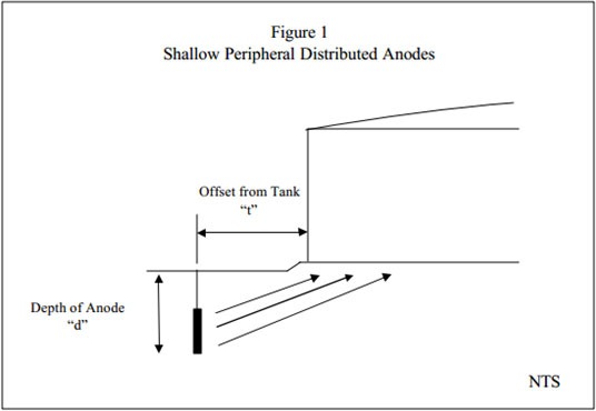
Shallow Distributed Anodes around Tank Periphery:
One common design approach to AST bottom CP is to install a shallow distributed point anode system around the periphery of the tank (Figure 1). These are typically augured into depths of 5-10 feet. This design approach only works when there is no electrically isolating secondary containment liner under the tank.
For these designs, the critical issue is assuring that sufficient current reaches the center of the tank. Above ground storage tank bottoms are large bare surfaces requiring a lot of current. To assure that current distributes properly, the anode depth and distance from the tank are critical. Shallow peripheral anodes are not able to throw current to the center of all but the smallest of ASTs.
MATCOR generally does not recommend shallow peripherally distributed anodes for ASTs with tank diameters exceeding 20 ft (6 m) due to the quantity of anodes required and the risk of poor current distribution to the center of the tank.
Deep Well Anode Systems
This approach is based on using one or more deep well anode systems located well below the tank bottom to provide current uniformly to the tank bottom. This approach has some limitations in heavily congested plant environments where current can flow to other buried structures. When multiple deep wells are employed to protect more than one tank in a cluster, care must be taken to assure proper current distribution.
As with any deep well, there are concerns with drilling (typically 150+ feet to bottom of hole) including access issues for a drill rig, environmental concerns, permitting and handling of drilling spoils. Even with a deep well approach, when dealing with new construction, reference electrodes should be installed under each tank.
Many operators prefer a close coupled dedicated CP system for each tank rather than the blanket coverage afforded by a deep well system.
Should the design for the new construction tank utilize a containment liner that shields current (i.e. polyethylene liner), the deep well anode system cannot be used.
Distributed Anodes Below Tank Bottom
While not as common today, many older designs utilized individual anodes laid horizontally along the tank bottom and connected parallel to header cables exiting the ring wall. The economics of this design, both in terms of installation costs and material costs, are not favorable and this design has been dropped in favor of either a grid system or linear anodes in a parallel concentric ring arrangement.
The Grid™ System
Developed, patented and heavily promoted by Corrpro, this proprietary system involves laying out parallel titanium conductor bars and then running mixed metal oxide (MMO)ribbon anode perpendicular to the conductor bars. The MMO ribbon anode is field spot welded to the titanium conductor bar to provide both mechanical and electrical connections. Wherever the titanium conductor bars cross, they too must be field welded together. Power feeds (pre-assembled cables with a flat plate to connect to the conductor bar) are secured to the titanium bar in multiple locations and routed to the ring wall penetration.
Patented in 1991, this system continues to be used by Corrpro; however, it is a labor and QA/QC intensive installation process requiring significant field welding and on-site testing to assure electrical continuity. The attachment of the power feeds to the titanium grid is critical to the system reliability. From a design perspective, the spacing of the anodes and conductor bars must be sufficient to assure even current distribution.
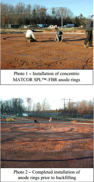 SPL™-FBR Linear Anode Systems
Unlike the Grid™ system promoted by Corrpro, MATCOR’s SPL™-FBR linear anode system for AST tanks can be factory assembled to eliminate the need for any field fabrication, which greatly simplifies installation and reduces QA/QC issues, eliminating field welds and power feed connections that are relied upon with the Grid™ system to assure electrical continuity and system integrity.
The principal advantage of the linear system is that everything under the tank is factory assembled and tested prior to installation and the only installation effort is to lay the anode assemblies in accordance with the design drawings and installation instructions. This provides for an exceptionally simple installation while assuring the highest system reliability; installation costs are minimal. Please refer to MATCOR’s Installation, Operation and Maintenance (IOM) Manual for a detailed installation description with pictures.
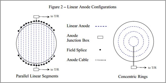
There are two primary configurations for linear anodes under tank bottoms as shown in Figure 2. The parallel linear anode arrangement has multiple parallel anode segments, which are fed from each end of the anode. The anode connections are field spliced to loop cables, which terminate at two anode junction boxes.
The use of concentric rings offers two key advantages over parallel anode segments. The first advantage is that this configuration does require junction boxes on both sides of the tank, thus eliminating one of the anode junction boxes and reducing the cabling required to run from two anode junction boxes back to the transformer/rectifier unit. The second key advantage to this configuration is that it eliminates the need for two field splices for each anode segment. Each ring can be manufactured with the appropriate length of header cable to run each end directly to the single anode junction box. These field splices are weak links subject to premature failure over the life of the anode system.
As with any system, spacing between anode segments is another key design element. MATCOR’s experience with ring configurations is extensive and we have determined through numerous installations and our own in-house testing that for tank bottom applications with bare bottom plates and an anode depth of 1 foot, concentric rings with a spacing of 10 feet provide thorough current distribution. When the anodes can be placed deeper than 1 foot, the anode spacing can be extended. Based on the 1 foot depth, typical ambient temperature tanks can be protected for 30+ years with 16 mA/ft linear anode, while a 50+ year design life is typically achieved with a 25 mA/ft rated anode with a modest 25% increase in the anode cost.
Provisions for Testing
With any tank bottom cathodic protection system, it is critical that provisions for testing be installed with the anode system. Once the tank is erected, making accurate potential measurements at various locations along the tank can only be accomplished if reference electrodes have been installed below the tank. Typically, copper-copper sulfate (Cu-CuSO4) reference electrodes are installed in strategic locations underneath the tank. These reference electrodes are often mistakenly called “permanent” reference electrodes; however, they are not permanent as over time the copper- copper sulfate solution becomes contaminated and ceases to provide accurate information. Once a baseline for performance is established over a sufficient operating period, maintaining the appropriate current output to achieve NACE criteria is all that is required.
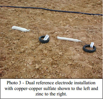 In some cases, clients may also specify dual reference electrodes such as both zinc and copper-copper sulfate. While the zinc reference electrodes are not as consistent, they provide a much longer operating life and can be calibrated against the copper-copper sulfate electrodes.
In addition to the fixed reference electrodes, it is also common to provide a reference electrode tube/conduit underneath the tank bottom to allow sliding of a calibrated reference electrode through the monitoring tube to take potential readings. These can also function as leak detection tubes.
Maintenance/Inspection
MATCOR typically recommends annual testing/inspection of the tank CP system by a qualified NACE CP level 1 or higher technician familiar with testing CP systems for ASTs. As with any impressed current system, monthly rectifier checks should be performed by plant maintenance to assure that the rectifier is on and that the voltage and current outputs remain stable.
Appendix A – MATCOR’S DESIGN PROGRAM
System Design:
Once all of the design parameters have been established, MATCOR’s design program uses the following process to create a completed design.
1. Basic Calculations
a. Tank Bottom Surface Area – simple geometric calculation of the area of a circle. If the tank bottom is coated MATCOR assumes a 75% coating efficiency (25% bare) as some coating degradation can be expected at all of the weld seams. b. Current Requirement – the bare surface area times the temperature corrected current density requirement provides the total design current required.
2. Anode Spacing – MATCOR typically assumes that the anode will be located a minimum of 1 foot below the tank bottom. Based on 1 foot depth, MATCOR uses 10 foot spacing between anodes. This is not based on any theoretical modeling but has been derived empirically by testing performed by MATCOR and validated on numerous actual applications. MATCOR has researched the available literature and has not found any published data or theoretical modeling that can be used to determine current distribution for concentric rings beneath a storage tank bottom. For depths greater than 1 foot, MATCOR increases the anode ring spacing at a rate of 0.5 feet/additional foot of depth.
Occasionally, clients have asked MATCOR to provide a theoretical basis or some sort of calculation to confirm the spacing of the anodes. NACE, in its CP3 design course, provides a geometric guideline of 2*tan60 for spacing of galvanic ribbon anodes under a tank bottom to assure distribution; however, we 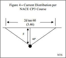 have found no reasonable scientific or theoretical explanation as to how this value was selected (Figure 4).
We have discussed this with NACE instructors and Senior Corrosion Engineers and they cannot provide any justification for this calculation. It just makes for a nice geometric value.
MATCOR has tested numerous tanks with impressed current CP systems using 10 foot spacing between anodes with a depth (d) of 1 foot. This equates to a geometric equation of 2d tan(78.7), which is not as elegant a number as 60. But we know from our testing using reference electrodes that have been placed inclose proximity to the tank bottom that current distributes sufficiently to meet NACE criteria between ring segments.
3. Current Capacity – once the preliminary anode spacing is determined, the total number of rings can be calculated with the rings spaced equally apart in concentric circles. The total anode length is then calculated. The current rating of the anode is a function of the total current required divided by the anode length.For ambient temperature tanks, using 10 foot spacing, the typical design requiresMATCOR’s SPL™-FBR-16 mA/ft anode and yields a 30+ year design life. The same design using MATCOR’s 25 mA/ft anode will generally provide for a 50+year design life for only a modest increase in material cost.
For elevated temperatures MATCOR calculates a temperature correction factor based on increasing the current required 25% for every 10° C above 30° C. To accommodate the higher current requirements at elevated temperatures, either a higher output anode is necessary or tighter spacing with more anode length is required. MATCOR’s design program allows for the anode spacing to be adjusted to optimize the anode length and anode rating as needed to meet the desired design life requirements.
4. Anode Resistance Calculations – each anode ring is connected parallel to one another through the anode junction box to the rectifier. The resistance of each anode ring is calculated using Dwight’s equation for a ring of wire:
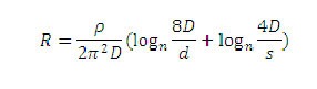
where:
R= resistance of each ring
? = soil resistivity
D = diameter of ring
d = diameter of anode
s = twice the depth of anode
Each ring’s resistance is calculated and then the total resistance is calculated as:
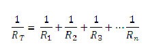
It is important to note that the resistivity directly impacts the resistance calculations and that often the actual sand resistivity can vary from the design basis affecting the resistance calculations and rectifier sizing.
5. Design Life – MATCOR’s linear anodes are rated for 20 years at the rated output of 16 mA/ft. The actual design life is calculated based on the design output divided by the rated output times 20 years to provide a calculated design life at design output. For ambient temperature tanks, the design life is typically around 30 years for 16 mA/ft rated anode and 50+ years for the 25 mA/ft rated anode.SPL™-Anode
TANK BOTTOMS CALCULATIONS SHEET
| Design Information | ||
| Tank Diameter | Ft | 120 |
| Current Density | mA/sq ft | 1 |
| Sand Resistivity | ohm-cm | 50000 |
| Depth of Anode | ft | 1 |
| Tank Operating Temperature | ºF | Ambient |
| Rectifier Margin | % | 20% |
| Cable Tail Length | ft | 20 |
| Design Results | ||
| Surface Area | sq ft | 11304 |
| Temperature Correction | 1 | |
| Factor | ||
| Corrected Current Density | mA/sq ft | 1 |
| Current Required | amps | 11.3 |
| Total Number of Rings | 6 | |
| Anode Spacing | ft | 10 |
| Anode Selection | 16 mA/ft | |
| Anode Life (est) | yrs | 32 |
| Total Resistance | ohms | 2.8 |
| Rectifier Sizing | voltage | 40 |
| amperage | 15 | |
| Total Anode Length | ft | 1130.9 |
| Total Cable Length | ft | 600 |
Ring Configuration
| Ring # | Diameter ft | Linear ft | Total ft | Cable Tail Length ft |
| 1 | 10 | 31 | 31 | 150 |
| 2 | 30 | 94 | 126 | 130 |
| 3 | 50 | 157 | 283 | 110 |
| 4 | 70 | 220 | 503 | 90 |
| 5 | 90 | 283 | 785 | 70 |
| 6 | 110 | 346 | 1131 | 50 |
Typical AST Tank Ring Cathodic Protection System
AST Cathodic Protection System Detail Drawing


