Last month, MATCOR successfully completed the first ever HDD tank cathodic protection system installation in the Middle East, utilizing a replaceable anode system.
Background—Initial Recommendation for HDD Cathodic Protection System
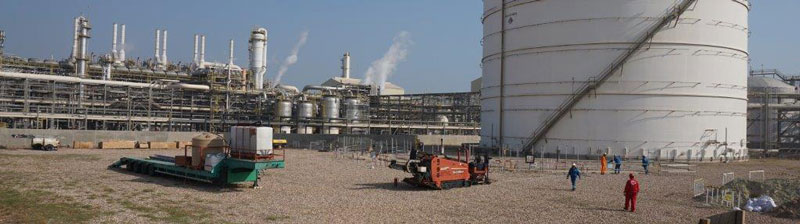
Equate Petrochemicals is one of the world’s largest producers of Ethylene Glycol. They initially contacted MATCOR in 2012 to discuss options for cathodic protection on a critical service Ethylene storage tank at their flagship Kuwait petrochemical facility. This tank was originally constructed in 1995, and the initial CP system installed with the tank was no longer providing sufficient current to achieve NACE Criteria. At the time, MATCOR suggested installing anodes directly under the tank using horizontal directional drilling technology. The plant’s engineering and operations team had significant reservations about this approach. The tank was critical to the plant’s operation and could not be taken out of service. Should the HDD operations result in damage to the structural integrity of the tank, the results would be catastrophic.
Perimeter Anodes—An (Unsuccessful) Alternative Approach
As a result of Equate’s concerns in 2012, they attempted an alternate approach, suggested by others, using perimeter anodes. Discreet anodes were installed offset around the perimeter of the tank—thus avoiding any possible risk to the tank during the anode installation. The use of perimeter anodes around larger diameter tanks is generally not a good idea. This is because it is very difficult to drive current to the center area of the tank, often resulting in adequate protection levels only for the outer edges of the tank bottom. For the Ethylene Storage Tank, the presence of heating pipes below the tank bottom only exacerbated the current distribution challenges. Ultimately, the results were not satisfactory.
In 2018, the plant engineering team reached back out to MATCOR to discuss our HDD solutions.
Replaceable Anode System Solution
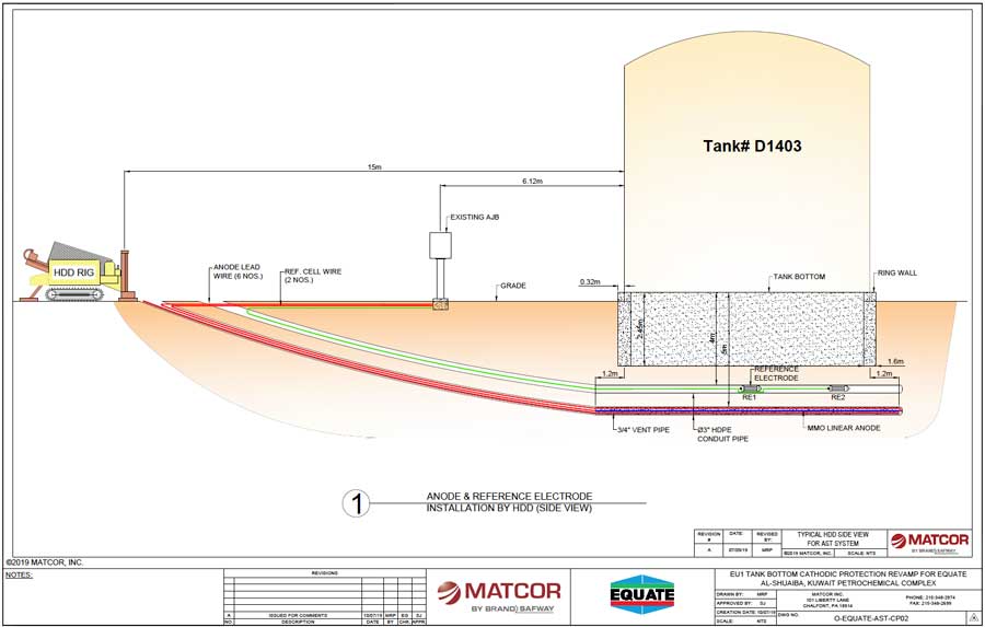
 MATCOR provided the plant with a detailed proposal to design and install a complete cathodic protection system using MATCOR’s Replaceable Tank Anode system. The RTA system is based on installing MATCOR SPL linear anode assemblies in a series of parallel slotted PVC pipes that have coke backfill pneumatically blown into the PVC pipe as part of the anode system installation. In addition to the linear anode segments and coke backfill, the slotted PVC pipes have a venting system to allow gases produced during the cathodic protection reaction to vent. This prevents gas buildup and blockage inside the PVC anode pipe.
One of the key advantages of the RTA system is that once the PVC tubes are installed, it is possible to flush out the anode assemblies and coke backfill should the anode assemblies fail and/or they are at the end of their design life making this a replaceable anode system that will assure cathodic protection for the entire service life of the tank.
Additionally, a slotted Reference Cell Tube would be installed to allow for two calibrated fixed cathodic protection reference electrodes to be inserted for full polarized and non-polarized potential measurements across the entire tank bottom. This would allow for testing of the CP system with calibrated reference electrodes for the life of the tank.
Experienced HDD Installation—Assuring a Safe Installation
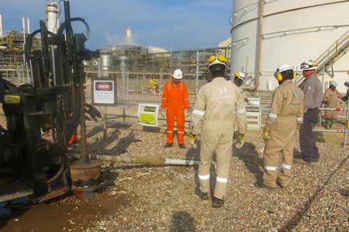 While the plant conceptually agreed with MATCOR’s solution from a technical perspective, there remained a significant concern within the plant’s operation and safety groups about drilling under this critical service tank and the possibility of a catastrophic event should the drill head drift up to the tank bottom. MATCOR put together a thorough installation procedure including detailed information on the sophisticated drill head tracking systems being utilized to assure that the drill head location was being continuously monitored throughout the bore. Utilizing an experienced local HDD drilling sub-contractor, MATCOR deputed its senior HDD installation drilling supervisor to Kuwait for the installation. Our Senior HDD Drilling Supervisor has completed hundreds of tank HDD installations in the United States and his on-site presence, along with the advanced electronic tracking package being used, assured that each bore went as planned.
Replaceable Anode System Installation Complete!
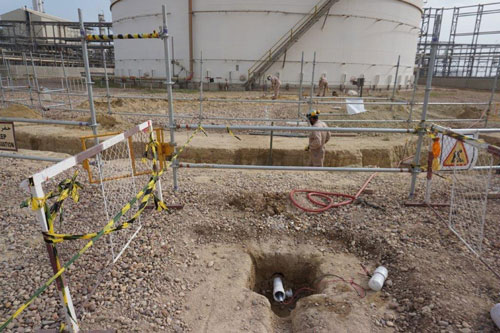
In December of 2019, MATCOR, working with our local Kuwaiti sub-contractor and the client’s engineering, construction and safety teams, successfully completed the installation of the replaceable anode system. The initial commissioning results showed that the anodes were installed properly. Each anode was distributing current as expected, and the polarization levels were meeting appropriate NACE criteria. The system has been left to operate and fully polarize. A subsequent visit by MATCOR’s technical team is scheduled in early 2020 to make final adjustments to the anode system current output and to confirm that the system continues to meet NACE criteria.
Conclusion
MATCOR’s successful installation in Kuwait of a horizontal directional bored CP system under an existing critical service tank is a first for the Middle East Region. The innovative MATCOR design, combined with the technical knowledge and operational expertise, makes this an interesting and viable option for other tank owner/operators worldwide to consider for their existing tanks with CP systems that are not performing properly.
To get in touch with our team of cathodic protection and AC mitigation experts for more information, to ask a question or get a quote, please click below. We will respond by phone or email within 24 hours. For immediate assistance, please call +1-215-348-2974.
Contact a Corrosion Expert
 MATCOR can help.
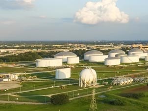 Evan Savant,
  This article describes the components of a

 At MATCOR, we pride ourselves on being a world class manufacturer of unique
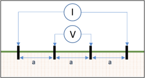
 One of the most important design parameters when considering the application of cathodic protection for buried structures is the resistivity of the soil. Soil resistivity testing is an important consideration for assessing the corrosivity of the environment to buried structures. It also has a tremendous impact on the selection of anode type, quantity, and configuration. Thus, it is critical that the CP designer have accurate data on the soil conditions at both the structure and at any proposed anode system locations. The lack of sufficient soil resistivity data can render a cathodic protection system (CP system) design ineffective and can result in costly remediation efforts during commissioning.