Category Archives: Cathodic Protection

Three Approaches to Cathodic Protection of Buried Pipelines in New Plant Construction

Cathodic Protection for Underground Piping Overview

Pipe Cathodic Protection | Cathodic Protection for Underground Piping | Steel Pipe Corrosion Protection Methods
Steel Pipe Corrosion Protection Methods: Deep Anode, Shallow/Distributed Anode Bed and Linear AnodeCathodic Protection

This article reviews 3 steel pipe corrosion protection methods utilizing cathodic protection.

Cathodic protection, when applied properly, is an effective means to prevent corrosion of underground plant piping. For many underground applications, such as pipelines, cathodic protection system design is relatively straightforward. Plant and facility environments, however, are not simple applications. Plants have congested underground piping systems in a tightly spaced footprint. The presence of copper grounding systems, foundations with reinforcing steel embedded in concrete, conduit, utility piping and structural pilings (either bare or concrete with reinforcing steel) can greatly complicate the task of designing a pipe cathodic protection system.

For simple plant facilities, it is possible to isolate the piping and utilize a conventional galvanic corrosion prevention system. This works only if the plant piping is electrically isolated from other underground structures for the life of the facility. For most plant and facility applications, it is not practical to isolate the piping from the grounding system for the life of the facility. In these cases an impressed current anode system is the only alternative.

3 Methods of Cathodic Protection for Underground Piping and Structures

There are three basic approaches to cathodically protect underground piping and structures using impressed current anodes.

  1. Deep Anode

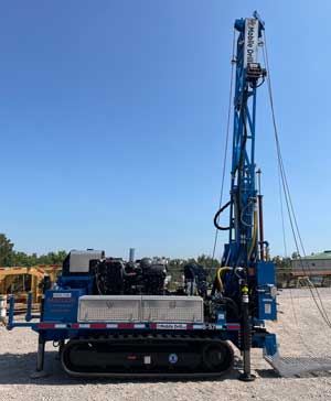
    One method is the deep anode in which high current capacity anodes are installed from the structure in a deep hole drilled vertically 150+ feet deep. This is analogous to lighting a football field with floodlights.

  2. Shallow Anode or Distributed Anode Bed

    Another method is to use a shallow ground bed anode design where many smaller capacity ground bed anodes are spaced near the intended structures – analogous to street lamps lighting a street.

  3. Linear Anode

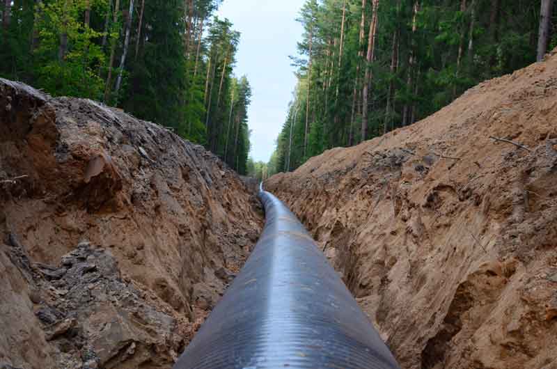
    The third method is to place a linear anode parallel to and in close proximity to the piping to be protected discharging current continuously along its length – similar to fiber optic lighting.

This technical bulletin details the advantages of using the linear anode approach for new plant construction projects to protect buried piping in a congested environment. This approach provides the most effective solution both technically and commercially.

Pipe Cathodic Protection Design Issues for Plants & Facilities

Electrical Isolation in a Congested Plant Environment

Electrical isolation is a major concern when designing a CP system for any plant or facility application. Isolating a single cross country pipeline segment from point A to point B is achieved rather simply through the use of electrical isolation flanges/isolation joints that the pipeline operator maintains and tests regularly. The realities of power plant piping networks, on the other hand, significantly complicate electrical isolation. By code, everything above grade in a plant must be grounded, yet it is common to see pipe cathodic protection systems designed based on isolation of the buried piping. Even if electrical isolation is achieved during the plant construction, maintaining electrical isolation over the life of the facility may not be realistic. Given the speed and complexity with which new plants are erected, achieving electrical isolation during construction is no simple task. Once installed, electrical isolation flange kits require regular monitoring and periodic replacement that often does not occur. Piping modifications and other plant maintenance activities can also result in an inadvertent loss of electrical isolation. Cathodic protection for underground piping that relies on electrical isolation should be avoided for plant applications.

Current Distribution – a Critical Issue in Pipe Cathodic Protection Design

Another critical issue that must be properly considered during the design of a CP system for plant applications is the highly congested underground environment and the challenges of achieving thorough current distribution. Buried piping is often located in congested underground areas in close proximity to grounding systems, foundations with reinforcing steel, pilings systems, metallic duct banks and other structures that can shield current from the piping systems that are the intended target of plant cathodic protection systems. It is virtually impossible to assess where current will go in a plant environment – the more remote the anode source, the more difficult it is to assure appropriate current distribution.

Stray Current

When discussing current distribution, it is also important to discuss the potential for stray current. For grounded systems, current that is picked up by other buried metallic structures is merely current that is wasted and not available to protect the intended buried piping structures. For isolated metallic structures, such as foreign pipelines, ductile iron piping systems, and nearby facilities or structures, stray current may be a significant concern. Stray current problems occur when current is picked up on an isolated structure and later discharges off that structure and back to a grounded structure. At the location where stray currents discharge, rapid corrosion may be inadvertently induced on the isolated structure.

The Case for Linear Anode Cathodic Protection System Design

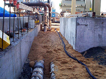
The linear anode solution consists of long runs of linear anode installed parallel and in very close proximity to the piping being protected. The current output is kept very low and is generally consistent across the entire system. A linear anode is in effect a distributed system with an infinite number of anodes spaced continually. This system provides the best technical cathodic protection solution and minimizes the current output required as follows:

  • Does not require electrical isolation.
    Because the linear anode is closely located next to the piping being protected, electrical isolation is not a significant concern. The anode is “closely coupled” to the piping and operates with a very low anode gradient that minimizes any losses to nearby structures including grounding.
  • Assures good current distribution as the anode runs parallel to the piping being protected.
    The linear anode cathodic protection system design eliminates any requirement for supplemental anodes to address areas where remote anodes may be shielded after the CP system is commissioned. Wherever the piping goes, the linear anode follows in the same trench. This also makes it very easy to adapt the design during piping revisions that may change the piping system routing as the plant construction proceeds.
  • Eliminates risks of stray current.
    Close proximity to the piping being protected significantly limits current losses to other structures and virtually eliminates shielding and stray current concerns. This also significantly reduces the total current requirements for the system, reducing the rectifier requirements.
  • Access issues – the linear anode is installed in very close proximity to the piping that is to be protected.
    This minimizes the risk of third party damage and reduces trenching required for buried cable. If installed in conjunction with the piping, the anode can be placed in the same trench as the piping affording the anode protection by the piping itself from external damage. This is a very cost effective cathodic protection installation when installed concurrently with the piping.
  • Ease of installation – when installed alongside the piping as the piping is being installed, the installation is simply a matter of laying the anode cable in the trench.

Our experts are happy to answer your questions about cathodic protection for underground piping.

Contact a Corrosion Expert

Explore BrandSafway’s Technical Seminars and Specialty Services

Industrial Specialty Services Technical Seminars

BrandSafway seminars provide you with in-depth knowledge and practical skills across a wide range of topics. Each seminar includes a 1-hour educational session, a tour, and lunch. MATCOR-specific seminars offer specialized training in cathodic protection and rectifier management:

  1. Cathodic Protection 101: An introduction to cathodic protection, its principles, techniques, and its application in preventing corrosion. This seminar is perfect for those new to the field or looking to refresh their knowledge on preventing corrosion in various structures.
  2. Rectifier School: Comprehensive training on rectifier operation, maintenance, and troubleshooting for effective cathodic protection systems. This seminar is ideal for corrosion technicians responsible for impressed current rectifiers.
  3. AC Interference and Mitigation: A detailed introduction to AC interference and mitigation for engineers and corrosion professionals, focused on practical theory and solutions.

For a full list of BrandSafway’s technical seminars, click here.

To request a lunch and learn seminar, please email matcorsales@matcor.com or call Lisa Porter at 215-327-3002.

BrandSafway’s Specialty Services

At BrandSafway, we pride ourselves on being the leader in industrial specialty services, offering unparalleled expertise and the largest fleet of scaffolding and access equipment in North America. In addition, MATCOR maintains the largest fleet of construction equipment for cathodic protection projects. Whether your project is large or small, our innovative solutions and dedicated team are here to ensure you meet any challenge safely and efficiently.

As part of BrandSafway, MATCOR specializes in providing advanced corrosion protection, including cathodic protection and AC mitigation solutions. Explore our brochure to learn about how BrandSafway and MATCOR can support your unique needs with industry-leading services and equipment.

View the Brochure

For more information, to ask a question, or schedule a seminar, please contact our team of corrosion experts. We will respond by phone or email within 24 hours. For immediate assistance, please call +1-215-348-2974.

Where to Find MATCOR in 2023?


MATCOR’s industry event calendar is jam-packed, starting right after the New Year!

You can find us at these upcoming events:

Contact us at matcorsales@matcor.com or visit our events page for more information to meet up at any of these events.

If you need assistance, please contact us. We will respond by phone or email within 24 hours. For immediate assistance, please call +1-215-348-2974.

Contact a Corrosion Expert

Steel Pile Corrosion: Protecting Our Solar Infrastructure

The US is constructing an increasing number of very large solar power generation farms, which brings about the question–what about corrosion? This new article explores solar farm steel pile corrosion. Do the buried galvanized steel piles supporting solar arrays meet service life requirements?


How do you protect the buried galvanized steel piles that support solar arrays from corrosion?
Galvanized steel pile corrosion can occur in as little as five years.

Big Footprint

We continue to construct an increasing number of solar power generation facilities. The United States plans even more as it continues to pursue policies encouraging renewable energy development.

The economies of scale make these facilities more competitive with other electrical generation technologies. These utility-scale solar farms have a capacity of anywhere from 1 MW to 1000+ MW. One feature of these solar farms is their physical footprint. The average solar farm requires 6-8 acres of land to support the tens of thousands of PV cells necessary to generate electricity at this scale.

For example, the Mammoth Solar Farm project in northern Indiana, once completed, will have a generation capacity of 1650 MW. And it will cover an area of 13,000 acres and use more than 2.85 million solar panels. This is the largest project in the US and should become fully operational in 2024.

Steel Piles That support Solar Arrays: What About Corrosion?

Given these facilities’ size, cost, and anticipated service life, a fair question to ask during the design phase is: what about corrosion? Specifically, the buried support structures that hold the solar arrays in place.

Typically, construction crews drive or screw galvanized steel piles into the soil to support the solar panels’ frames. Galvanized steel piles generally have a good service life in most environments for this application. However, as with all steel structures, they are subject to corrosion. Eventually, steel pile corrosion will adversely affect the support structure’s integrity.

Therefore, solar farm operators should consider the impact of corrosion on the service life of the galvanized piles during the project’s design phase.

Start with The Piling Details

The first step in the corrosion assessment process is to know your piles.

Any sizable solar farm project will require thousands of steel piles. The type of pile and the galvanizing thickness significantly impacting the project cost.

Unfortunately, structural engineers often do not consider corrosion when sizing the piles. They are keenly aware of loading concerns and select the pile to use based on a detailed soil load-bearing analysis and wind load analysis. They consider how big and how deep the piles need to be to support the predicted mechanical loads. This is often the only consideration. As a result, any conversation regarding corrosion is often relegated to – don’t worry, the piles are galvanized.

How Corrosive is the Environment?

But even galvanized piles are subject to corrosion, and in a highly corrosive environment, that service life might be much lower than expected. Therefore, additional corrosion mitigation measures, such as cathodic protection, might be warranted in some cases.

Given the massive footprint covering hundreds to thousands of acres these sites require, a thorough corrosion assessment for the entire area is warranted.

Typically, Geotech firms are contracted early in the project to perform detailed soil testing across these sites. This testing provides the requisite soil load capacity data to design the structural supports properly. While performing the site-wide testing, these firms will often perform some representative soil resistivity testing. While these sample soil resistivity tests may indicate the soil’s corrosiveness, they are often insufficient to evaluate correctly.

MATCOR Study: A Soil Testing Analysis

In one study performed by MATCOR, a comprehensive soil testing analysis found that much of a solar farm was in moderately corrosive soils. Still, a significant part of the facility was in very corrosive soils. In addition, the service life calculations varied significantly for the piles depending on their location within the solar farm. Estimated life ranged from 17 years to 30+ years.

Another factor in the service life calculations is the anticipated degradation of the piles during installations. The impact on the zinc coating can vary significantly depending on the soil characteristics.

MATCOR provides comprehensive soil resistivity testing services.

Steel Pile Corrosion: How Long Will the Steel Piling Last?

The first phase of the service life of driven steel piles is the outer zinc layer of the galvanized steel pile. Zinc acts as both a coating and a galvanic anode. As the zinc layer is consumed, the underlying steel substrate is exposed. Therefore, the estimated service life, in simple terms, is the anticipated service life of the zinc coating plus the expected service life of the steel substrate.

We define the service life for solar structural galvanized steel piles as some allowable percentage thickness loss before compromising the pile’s integrity.

There are a lot of factors that affect the pile’s corrosion rate, including:

  • Presence of copper grounding bonded to the pile
  • Degradation of the zinc coating during the driving of the pile
  • Differential soil resistivity strata
  • Differential oxygen levels/aeration
  • Location of the water table in the area of buried piles

One of the biggest drivers of accelerated corrosion for piles is the presence of copper grounding. When steel piles are connected to a copper grounding grid, their service life can be significantly reduced as the zinc coating layer and the underlying steel substrate act as galvanic anodes. This can be very impactful in low soil resistivity environments.

Significant Steel Pile Corrosion Can Occur in as Little as Five Years

In some extreme cases, corrosion of the galvanized piles can be structurally significant in less than five years of service. In most cases, the service life in corrosive environments can be anywhere from 10-25 years of service. A service life of more than 50 years in low-corrosivity soils might be achievable.

Solar farms are a growing part of our electrical generation portfolio and will continue to see substantial investments in the next several decades. Given the footprint and cost of these facilities, design engineers should seek corrosion assessments from qualified corrosion engineering firms such as MATCOR to confirm that the piling systems used to support the solar arrays meet the facilities’ service life requirements.

If you need assistance with galvanized steel pile corrosion protection, please contact us. We will respond by phone or email within 24 hours. For immediate assistance, please call +1-215-348-2974.

Contact a Corrosion Expert

Cathodic Protection Connections: Exothermic Welding vs Pin Brazing


Exothermic welding and pin brazing are two methods to connect a cathodic protection system to the protected steel structure. These connections route back to the rectifier to complete the circuit for an impressed current cathodic protection system. Or they connect to the anode lead cable in a galvanic anode system. They are an essential part of any cathodic protection system.

Exothermic welding and pin brazing cathodic protection connections resulted from historical needs in the railroad industry. In addition, both have a long history of use in the cathodic protection industry.

MATCOR has the experience and capability to use either connection technology depending on the client’s specifications or requirements. In the absence of a customer preference, MATCOR generally defaults to pin brazing for CP applications.

pipeline ac corrosion as290850090

Exothermic Welding for CP

The older of the two technologies is Exothermic or Thermite welding. More prevalent in United States specifications, this technology utilizes the heat generated from the reaction when you ignite a mixture of Aluminum powder and Iron Oxide III (ferric oxide Fe2O3). The resulting reaction is vigorously exothermic, generating temperatures more than 2000 C – sufficient to create molten iron.

Initially developed by German Chemist Hans Goldschmidt in 1893, exothermic welding connected steel rails on the Essen train line. In the 1930s, the technology gained widespread use for connecting bonding cables to railroad ties. This was thanks to the efforts of Charles Cadwell, a physicist for the Electric Railroad Improvement Corporation (ERICO.)

The Cadweld connection process has changed very little over time. It involves cleaning the structure surface down to the bare metal and laying the connector attached to the structure in a graphite mold. Next, you place an appropriately sized cartridge containing the aluminum powder and ferric oxide ready for igniting in the mold. Finally, using an ignitor sparks the reaction. As a result, an iron slug melts and flows over the copper conductor, welding it to the steel surface.

Cathodic Protection Connections: Exothermic Welding vs Pin Brazing

Pin Brazing for CP

Like exothermic welding, the railroad industry developed the second standard cable-to-structure technology—pin brazing.

In Sweden in the 1950s, high heat from thermite welding caused grain growth in the copper cable. As a result, connections to the rails were subject to fatigue failures from cyclical stresses associated with the movement of the rails as trains passed.

To solve this issue, the railroad industry developed lower-temperature joining technology using brazing. Brazing uses a range of silver-based filler metals to achieve the bond. These filler metals have a melting temperature between 620 and 970 C – well below the temperatures reached during exothermic welding.

Commonly specified in European standards, the pin brazing process has remained fundamentally the same since the 1950s, with some refinements to the equipment.

The pre-assembled welding pin and the pin brazing gun are the keys to pin brazing. The pin consists of a stud with a defined amount of flux encapsulated in the brazing metal. When you press the trigger, current flows through the pistol via the pin to the steel pipe. At the same time, an electromagnet is energized, drawing the pin holder and pin away from the steel surface, forming an electric arc. The arc heats the steel and starts to melt the tip of the pin. As a result, it causes the flux to melt and flow onto the steel. The electromagnet de-energizes when the current flow ceases, and the spring forces the molten stud onto the fluxed pipe surface. With the arcing stops, solidification is very rapid.

Comparing Exothermic Welding and Pin Brazing for Cathodic Protection Connections

Safety

Both methods are safe procedures when trained personnel follow the correct procedures. Neither method poses any environmental threat, although users should be sure to properly store and handle the thermite powder charges. For thermite welding, the process can be sensitive to moisture which could vaporize on contact with the molten iron slug. As a result, the potentially dangerous hot metal can be spat out of the mold. For this reason, you should conduct the pin-brazing process in damp environments and offshore applications.

Cathodic Protection Connection Reliability

Both connections have been used extensively and are widely accepted in cathodic protection. Unfortunately, no published data detailing the reliability of either connection technology exists, and reports of Cathodic Protection connection failures are infrequent and anecdotal. Lab testing on tensile load indicates that pin brazing is a slightly stronger bond; however, the loads at failure far exceeded any load possible in regular service. Nevertheless, both techniques will provide reliable, low-resistance connections when properly performed.

Metallurgical Effects

Both processes are thermal and will affect the metallurgical condition of the pipe. Many piping codes typically advise that the design consider the impact of any changes in the parent metal due to localized heating during the attachment process. Microhardness testing has shown that both connections are safe for the normal range of carbon steel pipe; however, some consideration must be given to thin-walled structures. Pin brazing results in lower temperatures and greater process control and should be considered for all thin-walled steel and alloyed piping.

Effects of Cathodic Protection Connections on Internal Coating and Fluids

Using thermal bonding to the exterior pipeline wall of a pipeline filled with highly flammable hydrocarbons requires some consideration. In addition, where internal coatings exist, it is reasonable to question whether or not thermite welding or pin brazing might damage the interior coating. Based on testing, the inner wall temperature rises more with thermite welding than with pin brazing; however, neither method’s results were sufficient to give any reason for concern.

If you need assistance with a cathodic protection assessment, please contact us. We will respond by phone or email within 24 hours. For immediate assistance, please call +1-215-348-2974.

Contact a Corrosion Expert

[ARTICLE] Cathodic Protection Failure

Restore, replace, extend, or do nothing?

In the Autumn 2022 issue of Tanks and Terminals, MATCOR’s Ted Huck delves into four strategies you can take when your cathodic protection system is no longer working.


MATCOR provides industry-leading cathodic protection and AC mitigation solutions to tank and terminal operators around the globe.


If you need assistance with a cathodic protection assessment, please contact us. We will respond by phone or email within 24 hours. For immediate assistance, please call +1-215-348-2974.

Contact a Corrosion Expert

MATCOR Adds a New Drill Rig to Our Fleet

Drill rig for cathodic protection installation

MATCOR is excited to announce the acquisition of a new drill rig to our existing fleet of HDD and vertical drill rigs.

Our newest rig is designed to be a cost-effective option for drilling shallow holes. The rig features a much smaller footprint than the conventional deep anode drill rigs used for installing Durammo® and other deep anode systems.

Drill Rig Features

The smaller and more agile auger rig allows MATCOR to be able to maneuver the rig in tighter areas than the full-scale vertical rig would allow. Additionally, the unit is available with a hollow stem drill pipe allowing us to lower anodes in place in environments where an open hole may not be feasible. The rig is capable of drilling holes down to 100 feet deep, but for hollow stem purposes, we are limited to a depth of only 50 feet.

What This Means for Our Future

MATCOR is excited to add this new rig to our industry-leading inventory of cathodic protection installation enabling us to better compete for:

  • Shallow conventional anode beds
  • Distributive anode beds around tanks and congested facilities
  • Mobility is increased since it is loaded on to a semi-trailer

For more information, please contact us at the link below, or reach out to your local MATCOR account manager.

Contact a Corrosion Expert

At What Distance Does Cathodic Protection Continue to be Effective?

This article explores the answer to a question posed by a student about the length of pipeline protected by a cathodic protection system.


What length of pipeline is protected by a cathodic protection system?

We recently received a question from our website from someone who self-identified as a Student. We love when people ask technical questions and are pleased that students visit the MATCOR website–we have always strived to have a content-rich website to help share CP knowledge. The question is as follows:

“For installed impressed current CP systems with 15 anodes, what would be the approximate radius/length of a 200-mile petroleum metal pipe that would be protected?”

So before diving into the answer, let’s frame this question with an assumption, identify some unknowns and provide a definition.

Assumption

The 15 anodes are part of a single anode bed. The anodes are electrically remote from the pipeline and connect to an appropriately-sized DC power supply (transformer/rectifier, solar power/battery unit, thermoelectric generator, etc.)

Unknown #1: Pipeline Details

Before doing any detailed engineering, there are a few details that must be specified:

  • Pipeline diameter and material of construction
  • Coating type and condition
    • The layout of the pipeline (location of pumping stations, valve stations, and metering stations)

Unknown #2: Soil Conditions

Understanding soil resistivity in terms of location, frequency, and spacing, is critical when designing cathodic protection systems for long-length pipelines.

Definition of Attenuation

a lessening in amount, force, magnitude, or value according to Merriam-Webster

When discussing at what distance cathodic protection continues to be effective along a pipeline, you must consider the attenuation of the CP current. At some point, the current diminishes along the length of the pipeline, becomes insufficient, and can no longer protect the pipeline.

The Answer: Impressed Current CP Systems are Complicated

We can effectively use attenuation calculations for signals generated on a uniform conductor and transmitted through a uniform environment.

In this case, the pipeline is not a uniform conductor; unless it is bare, it is anything but uniform. The coating has less than perfect effectiveness and an unknown number of defects distributed in an unknown manner. The environment is equally non-uniform; soil resistivities change based on location and weather changes. The more non-uniformity, the more inaccurate the results will be for any attenuation calculations.

It is virtually impossible to model mathematically for older pipelines with insufficient coatings. The only effective strategy is to collect data by installing a temporary current source to measure the effective current throw in each direction in multiple locations along the pipeline.

For new pipelines with very good coatings, it is possible to perform some attenuation calculations and empirically determine a reasonable separation distance between anode stations.

The math starts with determining something called the propagation or attenuation constant. To calculate this, take the square root of the resistance per unit length of the structure divided by the leakage conductance per unit length.

In Simple Words…

How hard is it for the current to travel along the pipeline versus how easy it is for the current to jump onto the pipeline?

The smaller this number, the further current will spread. Key factors affecting the attenuation constant include earth resistivity (higher resistivity soils mean further current spread) and coating quality (better coating means further current spread). Armed with this, there are six simultaneous equations that we can use, and that include hyperbolic sine and cosine functions.

Larger, new construction pipeline projects require you to consult with a professional engineer. A brief newsletter article will not adequately cover the mathematical gymnastics involved. We did say that the math is complex.

Well-coated, newer pipelines in moderate to high-resistivity soils can typically be protected for 20+ miles in each direction from an anode bed. Poorly-coated or bare pipelines in low-resistivity soils may require anodes every quarter mile or less.


Need more information? Please contact us at the link below.

Is My Tank CP System Working Correctly?


Ted Huck, Director of Manufacturing and QA/QC at MATCOR, recently published an article in the summer edition of Tanks and Terminals Magazine titled “Understanding Cathodic Protection Systems.” He explains how to assess the performance of cathodic protection systems for above-ground storage tank bottoms (Tank CP Systems).

When asked to summarize these performance assessments, Mr. Huck commented, “Tanks are pretty easy to test, except for those rare occasions when they are not. At that point seek professional help.”

Read the full article.


Need information or a quote for MATCOR tank CP systems? Please contact us at the link below.

Three Ton Sled Anode Assemblies Head to Beaumont, Texas

MATCOR shipped four of the heaviest customer sled anodes we have ever fabricated this month – over three tons each. Headed to Beaumont, TX, the anodes are part of a Gulf Coast refinery expansion project. The anodes will protect a variety of marine piling structures as part of a light crude processing expansion at the refinery.

Sled Anode assembly – pouring the concrete bases.

Each anode is rated for 75 amps and weighs approximately 6300 pounds. Each anode assembly consists of a pair of two-inch diameter Mixed Metal Oxide coated titanium tubular anodes, five-foot-long. The anodes utilize MATCOR’s proprietary tubular anode connection technology for larger diameter anode tubes. Each sled anode has two concrete bases resting on a common wood base fabricated with stout 6” x 6” pressure-treated wooden beams. The concrete ends include lifting lugs to support installation by crane either from land or on a work boat. The function of the treated wood beams is to sink into the sea floor.

Completed Sled Anode assembly – waiting on the concrete to cure.

The anode lead cables are dual insulated HMWPE/ Kynar 1/0 cables housed in a proprietary HDPE jacket and held in place along the sea floor using concrete weights.

Sled Anodes are an exceptionally cost-effective means of protecting large near-shore structures such as dolphins, jetties, pilings, and sheet pile walls. They are easy to install and even easy to remove in advance of dredging operations.

More Information About MATCOR’s Sled Anode Products

Marine Anode Sled Product Page

Houston Sled Anode Installation

[YouTube Video] MATCOR Sea-Bottom™ Marine Anode Sled

[Materials Performance Case Study] Impressed Current Anode Systems for Jetty Piling


Need information or a quote for MATCOR custom sled anodes? Please contact us at the link below.

Get News from MATCOR

Sign Up for Our Newsletter

    I understand my information will be stored securely for the sole purpose of conducting business with MATCOR, Inc. I agree to receive future email communication and understand that I may opt out at any time. View our Privacy Policy.
  • This field is for validation purposes and should be left unchanged.