 In June 2017, MATCOR’s parent company Brand Energy and Infrastructural Services joined forces with Safway Group to form one even greater company – BrandSafway – providing world class services to industrial, commercial and infrastructure companies through 350 locations in 30 countries. In January 2018, BrandSafway announced the formation of the “Integrity Services Group”, combining Midstream/MATCOR, LDAR and Industrial Specialty Services into one powerful group of over 500 employees, each uniquely qualified to supply our customers with safe, integrated and high-performing asset management and protection services, as well as regulatory compliance solutions.
All posts by MATCOR
AC Interference – Basic Theory | Video Training Course
What is the impact of AC interference on pipelines?
This 16-minute AC interference video training course reviews the 3 basic effects of AC interference on pipelines, including:
-
- 15-volt safety threshold
- Fault conditions
- AC induced corrosion
The summary below includes video timeline indicators so you can easily find your topic of interest in the video.
What is AC Interference?
(0:25*) AC interference is an interaction that occurs between high voltage power lines and pipelines in a common utility corridor.
*References the time in the AC Interference Video where this topic is reviewed.
1. Fault Condition Interaction Modes
In the video, our AC mitigation expert Ted Huck explains fault currents and two modes of interaction with pipelines, conductive coupling and stress voltage.
Conductive Coupling
(1:09) Conductive Coupling is a relatively rare occurrence when there is a fault condition along the power transmission line and a large amount of electricity is dumped to the earth. The collocated pipeline is subject to this discharge of electricity through arcing, defined as the flow of current through the soil. Although rare, conductive coupling can burn a hole through the pipeline and cause a catastrophic failure.
Determining the Safe Distance from Tower to Pipeline for Arcing
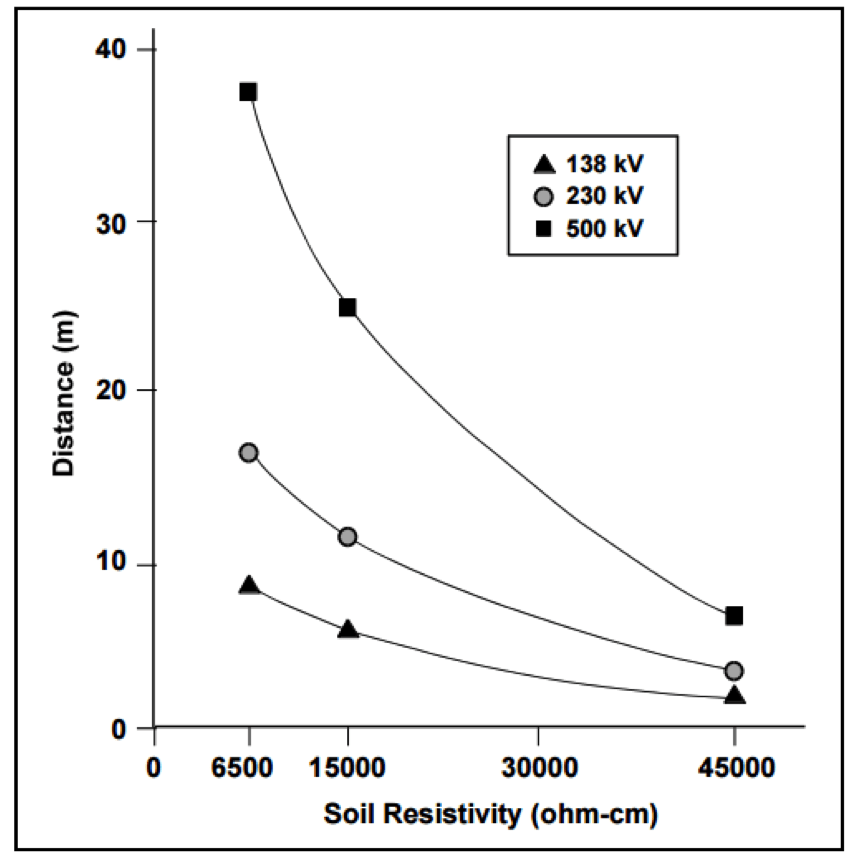
Arc Length
(2:16) In this segment, our AC mitigation expert describes a real customer case scenario where arcing caused catastrophic failure of a gas pipeline.
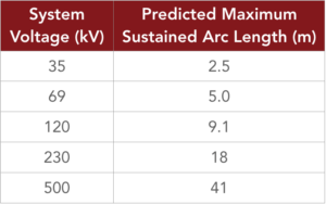
(4:01) Another issue that can occur with conductive coupling is a voltage rise radiating out from the location where the electricity is dumped to the earth. Newer pipeline coatings cannot handle excessive voltage stress.
Stress Voltage
Electromagnetic Induction
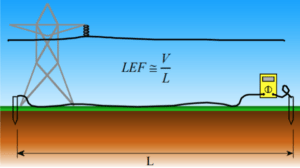
(5:44) Electromagnetic Induction is a steady state occurrence where current flowing through the line creates an induced current flowing in the opposite direction along the parallel pipeline. If the pipeline is close enough to the power transmission line, and runs parallel to it for some length, it will be in the electromagnetic field that exists around the AC transmission system. Being in that electromagnetic field, it will inductively pick up current throughout the longitudinal electrical field.
Longitudinal Electrical Field (LEF)
2. AC Induced Corrosion
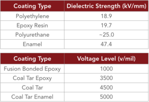
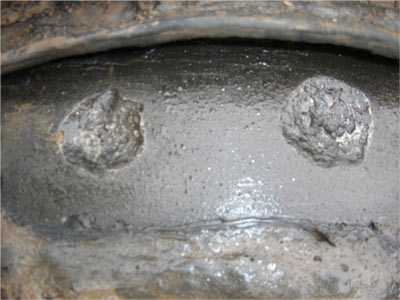
(7:26) AC induced corrosion occurs when alternating current is picked up by the pipeline that cannot effectively dissipate back to the earth. Well coated pipelines have very few places for the current to exit the pipeline and are at risk for significant, rapid AC corrosion. Older coating systems have many defects, or natural grounding points enabling AC on the pipeline to naturally dissipate, so AC corrosion is a relatively new concern. With newer coatings, AC current continues to build until it finds a small coating holiday (typically 1-3 cm2) to exit the pipeline, risking catastrophic failure.
How likely is AC corrosion to occur?
Current Density Formula

In our example, 4.4 volts AC is all it takes to cause AC corrosion. With older pipeline coatings that threshold is in the 15 volts AC range.
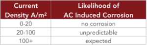
100 A/m² Threshold – When will AC corrosion occur?

Refer to NACE Report 35110, AC Corrosion State-of-the-Art: Corrosion Rate, Mechanism, and Mitigation Requirements for additional information about the 100 A/m2 threshold.
In Europe, refer to standard BS EN 15280:2013, evaluation of AC corrosion likelihood of buried pipelines applicable to cathodically protected pipelines.
The Relationship Between AC Induced Corrosion and Cathodic Protection
(12:00)
- No cathodic protection – high likelihood of AC corrosion
- Excessive CP current, or over polarization may increase AC corrosion

3. Safety
(12:50) Pipelines have above ground appurtenances such as valve stems and test stations that are subject to the AC currents picked up by the pipeline. These can pose a serious safety risk to workers, including shock or death. These risks are referred to as step and touch potential.
Touch Potential is defined as current flowing from touching an electrified device, through the body and down to the earth.

Step Potential can occur even without the worker touching the electrified device. In this case, current can flow up one foot, through the body and back down to the earth through the other foot, potentially causing serious injury or worse.
Refer to NACE SP0177-2014 (formerly RP0177), Mitigation of Alternating Current and Lightning Effects on Metallic Structures and Corrosion Control Systems, Paragraph 5.2.1.1 for additional information on the 15 volt safety criteria.
Summary
This AC interference video reviews the 3 basic effects of AC interference on pipelines, including the maximum 15 volt safety threshold—how much voltage can accumulate on the pipeline before it becomes a safety hazard to a person touching the pipeline? If there is more than 15 volts AC, we must do something to drop that voltage. Then there are rare but potentially catastrophic fault conditions, or the dumping of current to the earth. Finally there is AC induced corrosion, a result of the interaction of the electromagnetic field generated by current flowing through the lines and how it reacts with the pipeline. Pipeline operators must be prepared to mitigate these risks.
Have questions after viewing our AC interference video, or need a quote to mitigate the risks of AC interference? Contact us at the link below.
Additional Related Content
-
- AC Mitigation: 4 Approaches
- AC Modeling – The Basics
- AC Mitigation Overview
- The MITIGATOR® Engineered AC Mitigation System
- Engineering Report: Comparison of 3 AC Mitigation Methods (MITIGATOR, bare copper and zinc ribbon anode)
AC Modeling – The Basics
AC Modeling Overview
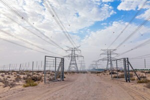
There continues to be much greater awareness by pipeline owners and regulators of the adverse interactions (AC Interference) that can occur between buried pipelines and above ground high voltage AC transmission systems that share some parallelism in a common right of way. When AC Interference conditions exist, it is important that the potential impact is evaluated and when necessary mitigated. For many applications, the most cost-effective approach to assess and mitigate the impact of AC Interference is to use a complicated computer AC modeling program.
The term AC Modeling really covers multiple modeling evaluations, as an AC corridor can often be quite complex. They may include multiple HVAC transmission systems and multiple pipelines in a common corridor or multiple shared right of ways along a long length of pipeline. Each may require its own AC modeling. In addition, the modeling looks at several different risks assessing how the pipeline is affected by steady state AC induced current, the impact of fault current along the pipeline and an evaluation of the impact of a fault current on above ground appurtenances to assure safe operation in accordance with IEEE std. 80 step and touch potential criteria.
Thus, it is very important for any successful AC modeling effort that the modeling software be of an extremely high quality and capable of properly handling the complex interactions of these various networks. The engineer or technician developing the model must also have sufficient experience and expertise to properly configure and operate the model, and evaluate the results.
AC modeling involves four key phases:
- Data Collection
- Creating the Model
- Establishing criteria
- Evaluating mitigation strategies
Data Collection
The data collection is critical to a successful modeling effort (the old adage garbage in = garbage out is quite applicable for these projects). The data requirements can be broadly broken out into three categories:
-
The characteristics of the AC Transmission Line(s)
- Physical geometry data on the tower including GPS location, height, # of AC circuits, tower configuration, height of each conductor, lowest point of each conductor, separation distance between conductors, shielding wire type and location, location of any phase transpositions, etc…
- Electrical data on the Transmission Line(s), including peak and average AC Load (in each direction), fault current max and duration.
-
The characteristics of the Pipeline(s)
- GPS location, depth of cover, coating type, coating resistance, pipeline diameter, pipeline wall thickness, location of all above ground appurtenances, location of all CP test stations and bonds to foreign structures.
-
The characteristics of the Environment
- Detailed soil data at multiple depths along the length of the pipeline, location of any crossings, presence/location of any foreign CP Stations or other interference conditions.
Collecting all the appropriate data often requires some field studies and working with both the pipeline owner(s) and the transmission line operator to get the required data. In some cases, the modeler cannot get all the required information and must make an educated guess – the accuracy of which can affect the quality of the results.
Creating the Model
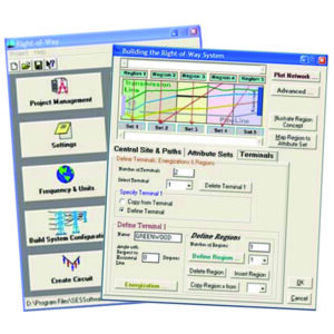
Once all the data is collected, the modeler creates the model space, detailing all the pipelines and HVAC systems and providing the requisite parameters associated with each of these elements. There are several commercially available AC modeling software packages that each have their own format for inputting the pipeline, transmission and environmental characteristics. Once the model has been built, it can take hours, days and in some cases weeks, of processing time to run simulations and for the model to provide the results of the simulation.
Evaluating the Model Results Against Established Criteria
The results of the initial model run need to be evaluated against the criteria that is established by the pipeline owner. In the absence of specific guidance from the owner, MATCOR’s default criteria are:
- No more than 20 A/m2 AC current density for mitigating AC corrosion during steady state induced AC current
- 3000 volts maximum coating stress during fault conditions for newer FBE type coated pipelines in accordance with NACE standard SP0177-2014
- 15 VAC for step and touch potentials at above ground appurtenances
For any given application, one or more of these criteria may be exceeded along the model’s area of analysis.
Adding AC Mitigation and Reevaluating the Modeling Results
Once the initial unmitigated results have been evaluated against the criteria that has been established, the modeler then adds, based on their experience with these systems, a mitigation scheme to the model with grounding at selected locations. This is often an iterative project where the model is run and the results evaluated and then if necessary, additional mitigation can be added or excess mitigation can be removed and the model rerun again in search of an “optimized” modeling solution that addresses all of the threats and results in meeting the requisite criteria.
Final Report
Once the AC modeling effort has developed a solution, the modeler develops a final report. Typical components of a final report include an introduction detailing the scope of the study, graphical illustrations of the pipeline(s) and transmission line(s) overlaid onto a satellite image, description of the modeling software used, detailed graphs/charts showing the results of the modeling, detailed drawings and bill of materials for the AC mitigation solution being recommended and appendices with the underlaying data.
Summary
AC Interference issues can be quite complex and modeling often offers the only valid way to assess and mitigate the risks from AC faults and steady state induced currents. When considering AC modeling it is important to look at the model being used and the modeler performing the evaluation.
Learn about our AC modeling and mitigation solutions:
Questions about AC interference, modeling or mitigation? Please contact us at the link below. Our experts are happy to help.
Contact a Corrosion ExpertAdditional Related Content
- AC Interference Video: Basic Theory
- AC Mitigation: 4 Approaches
- The MITIGATOR® Engineered AC Mitigation System
- Engineering Report: Comparison of 3 AC Mitigation Methods (MITIGATOR, bare copper and zinc ribbon anode)
6 Sled Anodes Replace 274 Galvanic Anodes for Marine Jetty Corrosion Protection
Marine environments can be some of the harshest environments on the planet for corrosion of steel structures. Indeed, the earliest application of cathodic protection can be traced back to Sir Humphrey Davy and the British Navy’s investigation into corrosion on copper sheathed wooden vessels. This video demonstrates MATCOR’s impressed current sled anodes that are successfully being used to protect steel piles for jetties, docks and other similar steel structures in marine environments.
At 1:03 in the video, we demonstrate how the marine anode sled operates with a trade show model.
At 4:05 you see a MATCOR Sea-Bottom Marine Anode Sled being lowered into the water as part of the cathodic protection system protecting a steel jetty structure in Indonesia. The jetty is constructed with four interior rows of concrete piles and an exterior row of 247 bare metallic piles. The operator initially considered galvanic anodes to protect the jetty from corrosion – until they compared the cost, time and effort to install the required 374 aluminum anodes each weighing 200 each. Instead they opted for six marine anode sleds, taking only three days to install.
For assistance with near shore marine anode systems, please CONTACT US.
Remediation Options for Aging Pipeline Coating Systems
A linear anode system may be an economical alternative to applying a new pipeline coating system or replacing aging pipelines.
by Ted Huck
Introduction: Addressing Aging Pipelines and Pipeline Coatings
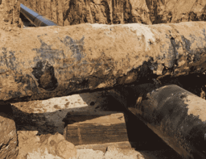 External corrosion is one of the significant threats facing pipeline operators worldwide. Historically, pipeline owners have employed a two-tiered approach towards mitigating corrosion risks. The primary defense against corrosion has been to apply a pipeline coating system that acts as a barrier, protecting the steel pipe from its environment. Cathodic protection is employed to supplement the coating system by providing protective current to the holidays or defects within the coating system. As with any aging structure, however, time takes its toll – for older pipelines this often results in an older coating system that starts to degrade in its primary function of protecting the pipeline from its environment.
This paper addresses the fundamental issue that many operators will face when evaluating their aging pipelines and pipeline coating systems. That issue is, quite simply, what is the best strategy to remediate an aging pipeline with deteriorating coating systems to maintain compliance with international standards for pipeline integrity. The options are to improve/upgrade the cathodic protection system, recoat the pipeline, or replace the pipeline. Each of these options will be discussed in detail and a decision matrix will be provided to facilitate the operator’s decision-making process.
Pipeline Coating Systems
Coating systems have been used on buried pipelines during the last hundred years and the technology continues to be the subject of significant research and innovation. Pipeline coating manufacturers are continually searching for better coatings to meet the varied needs of industry. Initially, the coatings were simple mixtures of crude pitches and solvents. These early bitumastic/asphaltic systems evolved into engineered coal tar enamel coating systems, which were prevalent into the 1960’s. The introduction of fusion-bonded epoxies (FBE) in the 1970’s quickly captured much of the pipeline market, although polyethylene, polypropylene and coal tar enamels are still used as well. The coatings industry continues to research and develop improved methods of providing more reliable and more economical coating systems.
When evaluating aging pipelines, coating condition is one of the critical issues that must be addressed. The coating provides the primary defense against pipeline corrosion and as the coating system ages and deteriorates, then the risks of corrosion increase exponentially. One of the challenges that must be addressed by pipeline owners is properly identifying the type and vintage of the coatings along a given pipeline. In many cases, different sections of pipeline may have different coating systems depending on the age of the pipeline and the standards in place at the time a section of pipe was installed.
Another critical consideration when evaluating aging pipeline coating systems is to identify whether the coating system fails shielding or non-shielding. Coating systems that fail in a non-shielding mode do not inhibit the flow of current making cathodic protection a viable alternative when considering how to remediate these lines. Other coating systems, principally tape coating systems, can fail in a manner that shields cathodic protection current and thus greatly reducing the possible remediation methods available.
Modern, over-the-line survey technologies have proven to be quite effective in evaluating coating quality and finding coating holidays. Technologies such as pipeline current mapping (PCM) which utilize a carrier signal transmitted along the pipeline with a receiver measuring the line attenuation along the pipeline length can accurately pinpoint areas of significant coating degradation even under concrete or asphalt. The information gathered using PCM in conjunction with pipe to soil close interval surveys (CIS) and direct current voltage gradient (DCVG) testing form the basis for identifying critical risk areas along aging pipelines. In-line inspection technologies using smart pigs also provide valuable data regarding coating quality.
Cathodic Protection
Pipeline coating systems are typically augmented by the application of cathodic protection. With a well-coated pipeline, cathodic protection can be economically applied to protect the coating holidays and defects by placing discreet anode beds that distribute current over long distances. In many cases ground beds can be located several kilometers apart and still provide sufficient current distribution to protect the entire pipeline. With some of today’s high technology factory applied coatings, the coating efficiencies are exceptionally high and the groundbed output requirements are very low. These discreet ground bed systems can either be deep anode ground beds or shallow ground beds located some distance off the pipeline.
Several issues must be considered when designing a cathodic protection system. These include coating quality, soil resistivity, available locations for electrical power, ground bed right of way issues, accessibility for maintenance, AC and DC stray current interference, and a host of additional issues. What is critical for aging pipelines is the regular evaluation of the effectiveness of the CP system. Frequently, as pipelines age and the coating quality begins to deteriorate, the CP systems are unable to provide sufficient current properly distributed to meet established cathodic protection criteria. In many cases, simply ramping up the output of the existing system or adding additional ground beds does not prove sufficient to address the problem.
Learn about soil resistivity testing.
Aging Pipeline Systems
Problem Identification
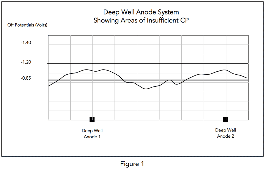
Aging pipeline systems with deteriorating coating systems suffer from poor current distribution and are characterized by areas of low potentials and exceedingly high levels of applied current density. The challenge with these pipeline systems is controlling current distribution to achieve the prescribed polarization levels consistent with international standards for adequate cathodic protection.
Figure 1 shows a deep well anode system with current output such that some areas are not meeting required off-potentials of -0.85 Volts to meet NACE criteria.
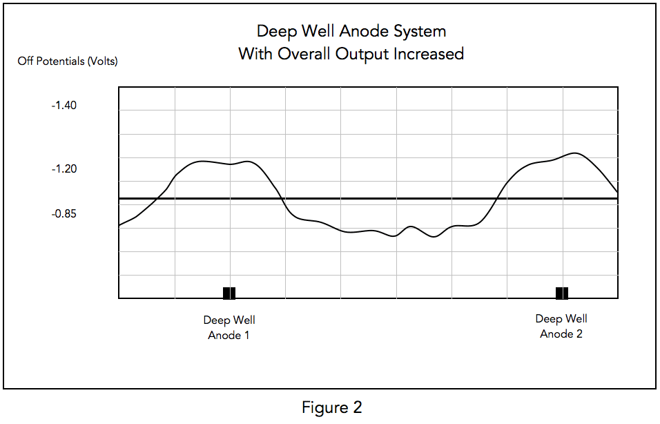
Initial Responses
The typical response to this problem is to increase the overall output of the deep well system (see Figure 2.) This generally does not alleviate the problems of not meeting the off-potential criteria and leads to over-polarizing the piping (potentials greater than -1.2 Volts.) This can result in coating disbondment further exacerbating the problem. The higher output current increases the ground bed’s consumption rate reducing operating life while raising operating costs appreciably. All this occurs without achieving the required levels of polarization to meet cathodic protection criteria.
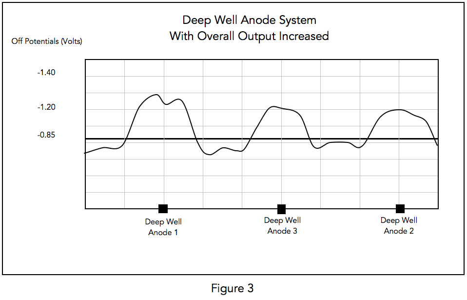
The next step that is taken to fix the cathodic protection current distribution problem is to add additional ground beds to reduce the distance between point sources. This too, proves to be an ineffective solution as the new ground bed provides only limited additional benefit (see Figure 3.)
Remediation Options
The problem cannot be economically resolved by the addition of an ever-increasing number of ground beds applying greater and greater amounts of additional current. The pipeline operator is then faced with a limited number of options: recoat the pipeline, replace the pipeline, or install a linear anode cathodic protection system.
Recoating/replacing is the only viable alternative for pipeline systems utilizing shielding type coatings such as tape wrap systems. Recoating costs typically run several hundred dollars per foot in open right of way areas and can be significantly more expensive in congested urban locations (these are ballpark numbers applicable to the United States and can vary significantly.) Recoating, when properly performed, can restore the pipeline coating system to an as new condition greatly extending the service life of the recoated section. The critical issue is to assure that the recoating is executed by an experienced coatings contractor with rigorous quality controls in place. Pipeline replacement is expensive and only performed when extensive third-party damage, significant corrosion or other extenuating circumstances warrant.
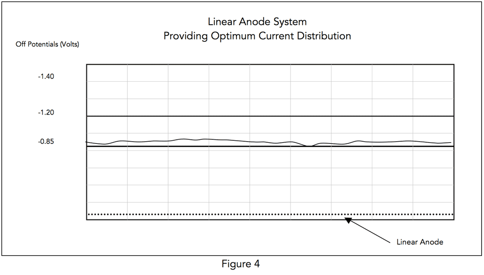
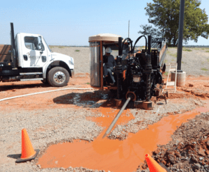
An economically attractive alternative to recoat/replace options is to utilize a linear anode configuration in lieu of point anode systems. This option is only viable when the coating system is non-shielding – this would include asphaltic and epoxy type coating systems. The application of a linear anode system typically costs between $20-30/foot in open right of way (again these are general price guidelines and can vary significantly.) In suburban or urban areas, horizontal directional drilling (HDD) can be an effective installation method with minimal surface disruptions. These linear anode systems eliminate the distribution problems experienced by point anode systems; they are in effect an infinite series of point anodes, which provide an optimum current distribution (see Figure 4.)
In addition to confirming that the pipeline coating system is non-shielding and appropriate for the application of linear anodes, the linear anode system design must take into consideration the critical issue of voltage drop and its affect on current attenuation. Voltage drop can have a significant impact on DC power distribution to the linear anode system. Ideally, rectifiers would be located no further than half a mile to a mile apart, however, practical considerations including availability of AC power, right of way issues and other factors can force this to be extended further complicating the system design and affecting the installed cost.
While the design can be complicated by voltage drop considerations, one of the benefits of a linear anode system is that the power consumption is relatively low. Ground bed resistance, as determined by Dwight’s Equation, is significantly affected by anode length and this results in very low groundbed resistance values for linear anode systems relative to conventional ground beds. This makes the linear anode system much more suitable for low wattage power sources such as solar arrays and thermo-electric generators (TEG’s) than conventional ground beds whose wattage could be two or more times that of a linear anode system to achieve the same current discharge.
Conclusion
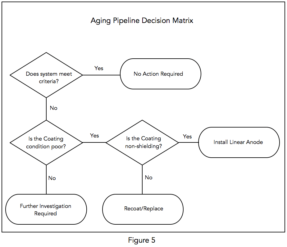
Aging pipeline systems with deteriorating coating systems present a difficult challenge to pipeline operators. The more the coating deteriorates, the more difficult it is to distribute current further away from the ground bed. The natural response to ramp up the ground bed output does an inadequate job of throwing current further but does result in increased current flow, higher current densities and over polarization near the ground bed further stressing the coating system. Adding additional ground beds also allows more current to be applied to the pipeline, but does not alleviate the current distribution issues. Ultimately, pipeline operators are faced with the choice of recoating/replacing the pipeline, or installing a linear anode system. The flowchart below (Figure 5) provides a decision matrix. Note that aging pipeline systems whose coating systems are determined to be in good condition through indirect and direct examination, require additional investigation to determine why criteria is not being achieved.
For assistance with evaluating aging pipelines or installing linear anode cathodic protection systems, please CONTACT US.
Selecting the Correct Linear Anode for Horizontal Directional Drilling (HDD) Installation
As the world’s leading manufacturer of linear anodes, and the only manufacturer of a linear anode specifically designed for use with horizontal directional drilling installations, we thought it would be appropriate to discuss various anode options for HDD installation.
Can any linear anode be used in conjunction with horizontal directional drilling?
 An engineer’s favorite answer to any question is “It depends” and this is certainly the case with HDD installations. The important thing to note is that when attempting to pull a linear anode through a bore hole, there is a chance that the pulling forces on the anode will exceed the strength of the anode and cause the anode to break. Even if the anode does not break completely, stretching of the anode can weaken or damage the internal header cable or anode to cable connections.
There are a lot of variables that can impact the success of any linear anode HDD installation. The short answer is yes, with the right bore hole, any linear anode can be pulled successfully. Conversely, with the wrong bore hole, any linear anode can be pulled apart during installation.
What are the key factors to consider when planning an HDD linear anode installation?
The key factors include a site geotechnical investigation, terrain and route mapping, and bore planning.
Site Geotechnical Investigation
Any discussion about HDD installation planning starts with a site geotechnical investigation. Obtaining a geotechnical survey or as much geological information about the respective jobsite is very important. A great amount of record information is available through sources including:
- United States Geological Society (USGS)
- National Geological Map Database
- Publications of the US Army Corps of Engineers
- Earth Explorer
- The National Soil Survey Center (NSSC) a division of the US Department of Agriculture
- State Departments of Transportation
- Highway Administrations
- Original construction records
In addition to record information, site-specific investigations (soil bores and soil sampling) by trained geologists and geotechnical service companies can provide valuable detailed data on the planned bore area geology. The geotechnical analysis should identify several relevant items including:
- Soil identification along the bore route to locate rock, rock inclusions, gravely soils, loose deposits, discontinuities and hardpan
- Soil strength and stability characteristics
- Groundwater
Local drillers with experience in the identified area can often provide valuable insight based on similar projects in the same area.
Terrain and HDD Route Mapping
Collecting accurate topographical information of the bore route is another critical component in the planning phase. Terrain and HDD mapping includes determining HDD bore hole entrance and exit locations, identifying and mapping elevation profile changes, ensuring that other utilities are appropriately identified and avoided, assessing the need for traffic control, evaluating any environmental considerations or limitations that might impact the use of drilling muds and hole conditioners.
Bore Planning Software
Several commercial bore planning software tools are available to assist in the planning phase. These programs utilize the soil and geotechnical data combined with the terrain and route mapping information to provide a graphic visualization of the job helping the driller more accurately “see” and perform the job from start to finish. These software tools help the contractor select the appropriate drill rig, drill bit type and back reamer based on the anticipated soil conditions and the total bore length. By choosing the drill stem and length, the desired bore path depth, desired minimum cover, diameter and bend radius of the product being pulled, the software plots a proposed bore pitch, calculates setback distances, figures point to point bore paths, estimates hole volumes and calculates pullback time. The software can also provide a fluid–mixing process map that shows how much mud should be used based on soil conditions, drill unit and tooling used.
If a bore planning software package is not used, field calculations should be performed to appropriately choose the correct drill rig, drill bit and back reamer tooling requirements, desired bore path and quantity and type of drilling fluids to be utilized.
What anode should be selected for HDD installation?

MATCOR manufactures two linear anode products (SPL-FBR™ Linear Anode and the Iron Gopher™) that are both, in the right circumstances, suitable for use in HDD installations. The installation contractor, along with the client, must carefully select the appropriate anode and the appropriate anode installation methodology. The two generally accepted methodologies are direct pulling of the anode through the properly conditioned borehole by attaching the anode to the backreamer after the initial pilot hole has been drilled. The second installation methodology involves pulling an HDPE pipe sleeve into the borehole, installing the anode inside the pipe, and then removing the HDPE sleeve. The tables that follow are intended to assist the installer in selecting the appropriate anode and installation methodology. The selection of the appropriate anode type and installation methodology is subjective based on a qualitative analysis.
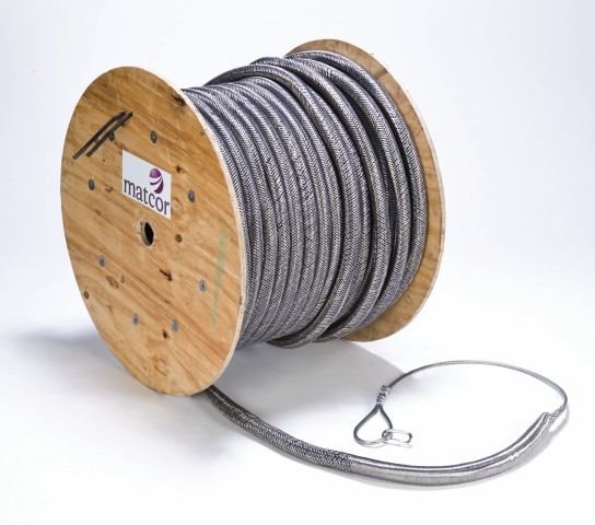
TABLE 1 – Linear Anode Application Difficulty
| EASY | • Less than 200 foot pulling length • Minimal changes in elevation • No environmental restrictions on use of drilling muds/hole conditioners • Installation costs and risks are low |
| MODERATE | • 200-500 foot pulling length • Moderate elevation change • No environmental restrictions on use of drilling muds/hole conditioners • Installation costs are modest and risks are low |
| DIFFICULT | • 500-1000 foot pulling length • Moderate elevation changes • Some environmental restriction on use of drilling muds/hole conditioners • Installation costs are higher and risks are moderate |
| EXTREME | • 500+ foot pulling length • Extreme or multiple elevation changes • Restrictive environmental limits on use of drilling muds/hole conditioners • Critical application with high costs and risks |
TABLE 2 – Anode Selection Guidelines
| Linear Anode Application Difficulty 1 | ||||
|---|---|---|---|---|
| SOIL TYPE 2 | EASY | MODERATE | DIFFICULT | EXTREME |
| Earth Loams | FBR | FBR/Iron Gopher | Iron Gopher | Iron Gopher* |
| Sand/Silt | FBR/Iron Gopher | Iron Gopher | Iron Gopher | Iron Gopher* |
| Clay | Iron Gopher | Iron Gopher | Iron Gopher* | Iron Gopher* |
| Gravel / Coble | Iron Gopher | FBR*/Iron Gopher* | Iron Gopher* | Iron Gopher* |
| Rocky | FBR*/Iron Gopher* | FBR*/Iron Gopher* | Iron Gopher* | Iron Gopher* |
*Anode is to be installed in HDPE sleeve that is then removed
NOTES
1Classifying the linear anode application difficulty using Table 1 is a qualitative analysis and may warrant taking into consideration other risk factors that may be appropriate. In general, the more difficult the application, the more costly the installation component, the greater the case to use the higher pulling strength Iron Gopher and the greater the incentive to use temporary HDPE sleeving to assure the lowest risk installation.
2Soil Types based on the US Department of Agriculture Soil textural classification guidelines. Earth Loams would include the broad range of Sandy Clay Loam, Loam, Silt Loam, and Clay Loam.
What contingency planning is warranted for an HDD installation?
Even with proper project planning and an experienced installation contractor, some consideration should be given to contingency plans if something unforeseen happens during the HDD boring and anode installation.
- Are alternate bits available if needed to complete the pilot hole?
- Is a larger boring machine available if needed?
- If drilling is more challenging than anticipated, do we have ready access to HDPE pipe for sleeving if warranted?
- Does the project warrant having one or more spare anode assemblies in the event of an anode breakage during installation?
While these risks can be greatly minimized with proper planning, asking these questions before mobilizing to the site can help solve problems more quickly, saving time and money.
For assistance with linear anode selection for HDD applications, MATCOR’s linear anode systems, project management or installation, please CONTACT US.
Tank Farm Design Recommendations for Corrosion Prevention
 Whether designing a few above ground storage tanks or performing tank farm design for an entire facility, proper consideration should be given to the adverse impact of corrosion that can occur on the tank bottoms. When addressing the issue of tank bottom corrosion, consider the environment, the tank size and design, and the type of tank foundation to be employed. There are definite advantages in certain materials based on the size and requirements of an above ground storage tank (AST) foundation. By carefully assessing the tank farm surroundings and long-term requirements, costly and potentially dangerous corrosion related tank failures can be avoided. Whether you are relying on a reputable company in the industry or taking on your own front-end engineering and design, there are across-the-board tank farm design recommendations to consider when it comes to corrosion prevention:
In terms of corrosion prevention for under ground storage tank (AST) foundations, is cathodic protection (CP) effective?
For tanks erected on compacted soil or sand foundations, with or without a concrete ring wall, cathodic protection is considered a “good engineering practice” and has been proven as an effective means of addressing tank bottom corrosion concerns. When you compare various methods of corrosion prevention for above ground storage tank bottoms, CP is shown to prevail over asphalt or concrete unless your project involves smaller diameter tanks. The corrosion failure rate is greater for tanks built on asphalt or concrete compared to tanks where a concentric ring cathodic protection system is installed.
In terms of corrosion, when is asphalt or oil/sand acceptable for above ground storage tank (AST) foundations?
Asphalt foundations are not common in the United States, as the mechanical integrity of asphalt can be an issue depending on the AST environment. As well, the use of oil/sand layer designs has been phased out by most tank owners in the United States due to the adverse impact that these oil/sand layers have on tank bottom cathodic protection systems. While historically prevalent in the Middle East and Asia, most larger national oil companies have abandoned this approach because it causes shielding of cathodic protection (CP) current, allowing corrosion to occur. Kuwait Oil, Aramco, and others now prefer clean sand combined with CP as the base material of choice. This is standard in the United States and has been for several decades.
What is a Concentric Ring Cathodic Protection System for above ground storage tanks (AST)?
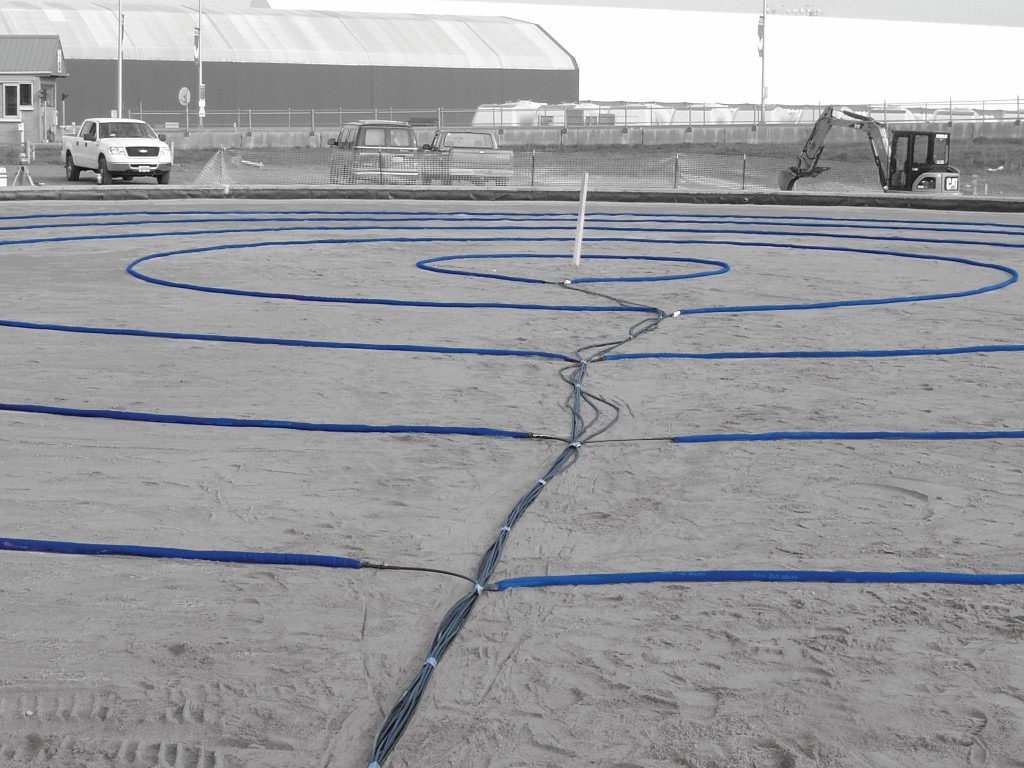
A. Designed for long-term storage, an AST cathodic protection ring system offers a factory-assembled design whereby the anode rings are ready to install with cable leads that extend past ring wall penetration. Concentric rings sizes are made to order, requiring no onsite welding, cutting, or splicing. The anode locations are marked, rings are laid out, and cabling is placed using a proven labeling system for future monitoring. A mixed metal oxide (MMO) anode is centered among a low-oxygen-generating coke backfill to eliminate depolarization.
Learn about MATCOR’s complete AST cathodic protection design services.
Are there some cases where concrete foundations are advantageous for tank farm corrosion prevention?
During installation of above-ground storage tanks, there are some advantages to concrete foundations for tanks when it comes to corrosion—the high pH of the concrete acts to passivate the steel, unless you have an above ground storage tank (AST) liner pad or something that is between the concrete and the tank bottom. If you can effectively seal the chime from the ingress of water and oxygen, the corrosion rates are generally quite small. Unfortunately concrete foundations for larger diameter tanks are not typically practical and can be quite expensive to properly install. Concrete foundations with appropriate AST liners are best for smaller diameter tanks.
In tank farm design for corrosion prevention, what are the best recommendations for above ground storage tank (AST) liners?
Plastic secondary containment liners are largely phased out in the United States and have been replaced by geotextile membranes that serve the same secondary containment purpose as plastic—they are conductive to allow cathodic protection (CP). The general standard in the United States is to have a CP system directly under the tank in order to minimize stray current or current losses due to earthing systems around the tank. Since the tank bottom is a large bare structure and the anodes are closely coupled to the tank bottom, there is usually very little current drain to other structures; the system if properly designed can accommodate modest current drain. While a plastic liner provides isolation from other nearby structures, when a problem arises with the CP system or if the CP system reaches the end of its projected service life, there is no way to install a new CP system without replacing the tank bottom.
Tank farm corrosion prevention is more manageable now than ever before. The MATCOR Concentric Ring Cathodic Protection System™ is just one of many excellent options for protecting your above ground storage tank (AST) from damaging corrosion.
For assistance with tank farm design, our Concentric Ring AST Cathodic Protection System™, project management or installation, please CONTACT US.
Learn more about Tank Cathodic Protection
- MATCOR Corrosion Experts Launch New App For Tank Cathodic Protection System Design
- Cathodic Protection Trends | Above Ground Storage Tanks
- External Tank Bottom Cathodic Protection
- Midstream Terminals – Cathodic Protection For Above Ground Storage Tanks (AST)
- Cathodic Protection Systems Vital In Above Ground Storage Tanks
- Tank CP Installation – A Drone’s View!
Tank Cathodic Protection Trends | Above Ground Storage Tanks
This presentation explores current tank cathodic protection trends, specifically for above ground storage tanks.
![]()
Statistics show owners of above ground tanks often experience external corrosion issues because of limited or poor installation methods. Typical above ground storage tank (AST) methods of the past involve a ring wall foundation that is generally formed with a sand or soil base, or even concrete for smaller tanks. It has previously been acceptable to use a galvanic ribbon anode system (generally magnesium), but this system often fails prematurely due to unstable sand-based foundations and poor connections. For this reason, the industry is moving away from the galvanic anode system and to newer concentric ring tank cathodic protection systems for above ground storage tanks.
Good Engineering Practices
While there are newer designs for AST cathodic protection systems, your first consideration should always be good engineering practices. The proper installation of a high-end tank cathodic protection system begins with known design specifications based on the tank size and diameter. This presentation compares traditional grid anode systems with newer linear anode concentric ring systems for the cathodic protection of above ground storage tank bottoms. In addition, congested terminal environments often lead to interference and less current at the tank bottom.
Grid Anode vs. Concentric Ring Tank Cathodic Protection Systems
While the field-fabricated and field installed grid anode system has been in use for over 20 years, some faults have been discovered. Field installation presents welding challenges for the contractor because the system must first be secured, and it cannot be installed directly over sheet liner. The ribbon anode and titanium conductor bars have to be field cut to the appropriate lengths. At the conductor bar to anode ribbon intersections, a weld is applied. The field assembled grid system is subject to weld failures, the spot welds can be damaged easily during subsequent sand installation, and care must be taken to hold the system in place so that it does not short to the tank bottom. All of these installation challenges can adversely impact the system performance. Additionally, bare MMO in sand is an oxygen generator when used for cathodic protection. Oxygen is a depolarizer and in some instances this can lead to issues with maintaining polarization criteria.
Advantages of the Concentric Ring System
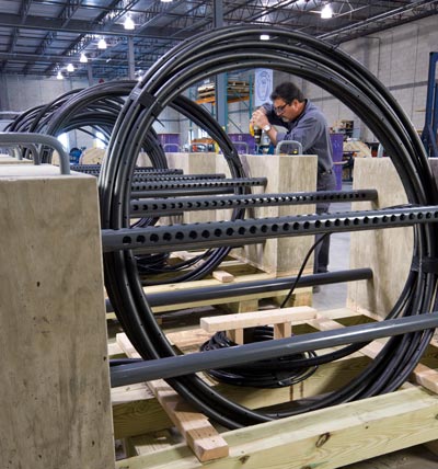
 In comparison, newer concentric ring systems for above ground storage tanks include factory assembled anode rings that come equipped with the appropriate cable leads to extend past the ring wall penetration. No onsite field assembly is required. The system is pre-assembled in concentric ring sizes designed for your tank and requires no cutting, splicing, or welding, and the MMO wire is backfilled within a braided fabric sleeve with coke breeze. Anode locations are simply marked, each ring is laid out at the proper diameter, and cabling is extended toward the ring wall. The anode cables are labeled for ease of identification and to allow for monitoring of current to each anode ring. Unlike the grid system, the MMO anode is centered in a coke backfill – this coke environment inhibits the generation of oxygen eliminating the issues with depolarization.
The concentric ring tank cathodic protection system is designed for longevity. A typical under-tank ring system using MMO anodes exceeds a 30-year life, however can be designed to extend life beyond 100 years.
Additional Considerations for Tank CP
- Some tank operators opt for a “replaceable” anode system, however time and manpower are required to extract and replace the anodes and backfill and the design life is only 30 years.
- Volatile corrosion inhibitors (VCI) are often used in conjunction with cathodic protection systems where CP cannot be installed or may be ineffective, such as ring wall crevices, poor bottom-to-sand contact, and more. It can be pumped under tanks via shielding high-density polyethylene (HDPE) containment liners.
Today, tank owners have more effective choices than traditional grid anode systems for tank cathodic protection. The MATCOR Tank Ring Anode™ System is trending as a high-end solution for above ground storage (AST) tanks.
For assistance with tank cathodic protection design, MATCOR’s Tank Ring Anode System, project management or installation, please CONTACT US.
Learn more about AST Cathodic Protection
- MATCOR Corrosion Experts Launch New App For Tank Cathodic Protection System Design
- External Tank Bottom Cathodic Protection
- Midstream Terminals – Cathodic Protection For Above Ground Storage Tanks (AST)
- Cathodic Protection Systems Vital In Above Ground Storage Tanks
- Tank Farm Design Recommendations For Corrosion Prevention
- Tank CP Installation – A Drone’s View!
Sled Anode Cable Connections
What is the best way to prevent damage to sled anode cable connections due to rough sea current and waves?
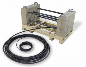
MATCOR marine sled anodes (Sea-Bottom™ Anodes) are designed with the cable connections routed inside a high density polyethylene (HDPE) protective pipe with holes to provide a level of mechanical protection. Then we use concrete weights to help secure the HDPE pipe (with the cable inside) to the sea bottom so that they are not subject to wave or tidal action.
 The protective housing is pictured here and called out as item 4 on the drawing on page 3 of our Sea-Bottom Marine Anode Sled brochure. For the concrete weights, you can use a variety of methods from sacks of concrete to custom formed concrete cast weights. Below is a photo of the weights that were locally supplied to us for a recent project in Indonesia. These weights are installed by divers during the sled anode installation.
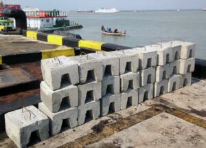
For assistance with impressed current anode system design, MATCOR’s Sea-Bottom Marine Anode Sleds, project management or installation, please contact us at the link below.
Contact a Corrosion ExpertApril 24 is Corrosion Awareness Day
Did you know that corrosion costs us an astounding 2.5 trillion dollars globally?
Not to mention corrosion can cost lives and jobs…
Today is corrosion awareness day, so we thought it would be a good idea to reiterate the importance of the NACE IMPACT (International Measures of Prevention, Application, and Economics of Corrosion Technologies) study released in 2016.
According to the study, most corrosion failures, and nearly all catastrophic corrosion failures are preventable. And nearly $875 billion can be saved through the right prevention and risk analysis efforts.
Through the IMPACT study, NACE determined that in order to reduce the astronomical cost of corrosion, we would have to change how decisions are made regarding corrosion. We must not only continue to develop corrosion control methods and technology, but we must utilize organizational management systems and risk tools throughout all levels of an organization to achieve the greatest success in saving lives, jobs and money.
You can learn more by visiting impact.nace.org.
Cathodic Protection Systems | Cathodic Protection Design | alternatives to sacrificial anodes and galvanic anodes


