Deep Well Anode System Design
OVERVIEW:
This technical bulletin addresses deep well anode system design for easy installation and reliable operation. For decades, Deep anode ground bed systems have been utilized for decades to distribute cathodic protection current to protect pipelines, storage tank bottoms, well casings and other buried structures. The design and installation practices of deep well anode systems have a significant impact on the life and performance of the structure. Conventional deep anode groundbed designs typically consist of multiple individual discrete anodes in a coke backfill. MATCOR’s Durammo® continuous MMO wire deep anode systems offer additional benefits for many applications and will also be discussed in detail.
Summary/Conclusion:
For deep well systems with outputs under approximately 75 amps, MATCOR’s Durammo® continuous MMO wire anode deep systems provides the greatest value. For those deep well systems with significantly higher current output, conventional multiple discrete anode designs are often the only option.
Overall CP System Design
This technical bulletin does not address the design of CP systems, but is focused on the actual deep well anode system design. Determining the current required to protect the specified structure(s), assessing locations for specific groundbeds, evaluating interference concerns,determining current attenuation, selecting power supply, etc., are all important design issues;however, they are beyond the scope of this bulletin. The purpose of this bulletin is to discuss the technical issues related directly to the design of the anode system.
There are three interrelated key performance issues when designing/evaluating a deep well groundbed:
- Groundbed resistance – deep well anode systems are commonly designed to produce 1 ohm or less resistance. Several factors influence groundbed resistance including soil resistivity, active area length, coke column quality, and anode consumption. Groundbed resistance often changes over time.
- Groundbed output – current output is a function of the power available as applied voltage and circuit resistance (Ohm’s law V=IR). Over time, as the resistance of the groundbed changes, the current output decreases unless more voltage is applied.
- System life – deep well groundbeds have a design life and they have an actual operating life. The design life is typically a calculated value based on the quantity of anode installed and the time required to consume the available anode at the design current. Actual system life can exceed the design life in some cases or may be much less than the design life as a result of poor design, premature component failure improper installation or from operating the system beyond its original design parameters.
Learn about MATCOR’s complete cathodic protection design services.
Anode System Design Issues
Hole Configuration– A deep well anode system consists of two zones – the active area,which extends from the bottom of the hole to the top of the coke column, and the inactive zone. Typically, the inactive area ranges from 50 ft to 100 ft (15m to 30m) and its purpose is to assure that the anode(s) are sufficiently remote from the structure to ensure good current distribution. The active area is where the anode(s) are located. There are several practical considerations that effect the sizing of the active area. First and foremost, the length of the active area has a significant effect on the overall groundbed resistance. Dwight’s Equation is used to approximate the resistance of a vertical groundbed. The two primary factors in the equation are groundbed active area length (L) and soil resistivity (?). The hole diameter (r) has only a nominal affect on the groundbed resistance (RA).

The second critical factor that dictates active area length is current output, which in turn determines the quantity of anode(s) required. The higher the current output required, the more anode that is needed and consequently the longer the active length required.
Dwight’s equation is based on several false assumptions – namely that the groundbed is a single vertical rod whose length is equal to the active length of the coke column and secondly that the soil resistivity is a constant along the entire length of the active area. Nonetheless, Dwight’s equation is a reasonably good tool for approximating groundbed resistance.
Anode Configuration – The selection of an anode type is an important consideration. There are two basic types of deep well anode configurations:
Discreet Anodes
In this configuration, multiple individual anodes are spaced within the deep well active area. The anodes must be spaced far enough apart to prevent mutual anode interface effects – typically a minimum of 10 ft (3m.) The exact number of anodes required is a function of the anode type, size, output requirements, and system design life. It is not uncommon to have 10 to 15 discreet anodes in a single deep well system design.
Continuous Anode Assembly
MATCOR’s Durammo® Deep Anode system utilizes a continuous wire anode in lieu of multiple individual discrete anodes. The continuous wire anode assembly is fed from two cables, one at each end. In addition, there are jumper cables every ten feet that are factory connected to the wire anode creating a series parallel effect. This provides electrical redundancy in the event of either an anode or cable failure. This also reduces the IR drop along the length of the anode and assures that current distributes evenly off the anode element.
Anode Material Selection – there are a range of commonly used anode materials available for use in deep well applications:
Graphite
Graphite anodes have been used since the 1940s and remain the anode of choice for many clients. While proven as a reliable product depending on design and environmental conditions, they have a relatively high consumption rate of two pounds per amp year (2 lb/A. yr.) and on a cost per amp/yr basis are the most expensive of the anode selections. Graphite anodes are available in two standard sizes for deep well applications; the 3”x 60”, weighing a nominal 28 lbs, and the4”x80”, weighing a nominal 66 lbs.
High Silicon Cast Iron (HSCI)
HSCI anodes have been employed since the 1950s and are also quite popular in deep well anodes systems. They consume at approximately half the rate of graphite anodes (1 lb/ A yr) and are typically available in 60” and 84” lengths with a wide range of diameters available with varying mass and operating life.
Mixed Metal Oxide (MMO)
MMO anodes have been used since the 1990s. MMO is a coating of rare earth oxides over a titanium substrate and are occasionally called activated titanium anodes. Unlike Graphite and HSCI, MMO anodes are dimensionally stable anodes that do not consume at the rate of pounds per amp year but instead act as a catalyst with a consumption rate of mg/A yr. MMO anodes are capable of operating at higher current densities. They are also lighter than conventional anodes facilitating installation. MMO is available in tubular and wire configurations for deep well installations.
Coke Column – The coke column plays a critical role in the performance of the deep well anode system. As noted previously, groundbed resistance is approximated using Dwight’s equation based on the assumption that the entire groundbed is a single vertical Trod. Placing the anodes in a vertical column of low resistance coke backfill allows current to discharge off the anodes and travel up and down the column. In theory this renders the entire active area into a single anode.
Typical carbon backfill commonly used in conventional shallow groundbed designs is chosen for its low cost. It tends to have relatively large particle sizes with a bulk density of approximately 60 lbs/cubic foot. Deep well groundbeds, however, should use higher quality coke specifically modified for deep well applications with a bulk density of 74lb/cubic foot indicative of a more consistent and smaller particle size. One of the common reasons for premature deep anode system failures is a poorly formed coke column. The quality and bulk density of the coke are critical factors that can affect the quality of the coke column.
How the coke column is installed also affects the performance and life of the groundbed. Pouring dry powder down hole, while quick, does not promote a quality coke column and can lead to air gaps, bridging and voids. The preferred method of installation is to use higher quality deep well coke designed for fluidizing and install that by pumping downhole and filling from the bottom. The higher density, smaller particle size means far fewer voids and air gaps. Additionally, this helps to prevent washing out of the coke column and promotes a more consistent, lower resistivity coke column. Loresco’s website notes that SC-3 deep well coke breeze provides up to 40% lower resistivity than other coke backfills. MATCOR firmly believes that a higher quality coke backfill is a critical component in assuring the longer life of any deep well system.
Some groundbed designers include the coke column in their life calculations since some percentage of the current transfer will be electronic discharge through the coke column and will result in the coke consuming and not the anode. Also, the typical operating output is usually less than the system design output. Actual experience is that the coke column will bear some of the consumption, that the anodes will not have 100% utilization and that the current discharge will not be uniform, with each anode having a significantly different discharge rate resulting in some anodes depleting faster than others. This is a commonly accepted premise and is the reason that many designs are “over-engineered” to include more anodes than are needed based on actual current requirements.
Vent Pipe Assembly – One of the characteristics of deep well anode systems is that they typically operate at relatively high outputs – they are designed to supply lots of current over a broad area. One of the potential reactions that occurs at the anode is the generation of chlorine gas from the dissolution of naturally occurring salts in the soil.The amount of chlorine gas generated is a function of the current density – the higher the current discharged the more chlorine gas that can be generated. Chlorine gas attacks cable insulation and eventually will aggressively react with the copper in the cabling system rendering the deep well inoperable.
For this reason, deep well anode systems typically have a vent pipe assembly, which is centered in the active area coke column and allows any chlorine gas formed at the anode to vent to atmosphere. Without a properly functioning vent pipe, chlorine gas can form and attack the cabling resulting in a premature system failure.
The common industry standard vent pipe utilizes micro slots that are cut into sections of 1” pipe (Loresco’s All-Vent™ or equivalent) as shown below on the right hand side.
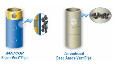
The slots are .006 inches by 1.5 inches and provide a total open surface area of .018 square inches per foot of vent pipe. MATCOR’s Super-Vent™ pipe assembly uses relatively large diameter holes with an inert fabric filter element to protect and greatly enhance the venting capability. The total open surface area of the MATCOR SuperVent™assembly is .098 square inches per foot of vent pipe. Since venting capability is a function of the square of the open surface area, our system is over twenty-five times more effective and is less prone to clogging.
Cabling – While the anode system is the core of the deep well system, the cabling is critical to the system’s performance. A failure in the cabling between the anode system and the rectifier renders the system inoperable – and in most cases there is no remedy as the cable and anodes are inaccessible once loaded down hole. Cabling is also one of the more expensive components of the anode system cost. Thus the choice of cabling is a critical design element. There are two common cabling systems used in deep well applications. The first is a typical direct burial heavy-duty polyethylene type cable insulation, which is not chlorine resistant. The second is a more expensive, dual extruded insulation system that adds a layer of chlorine resistant PVDF layer to protect against chemical attack (Kynar® and Halar® being the common trade names.)
Deep Well Anode System Performance
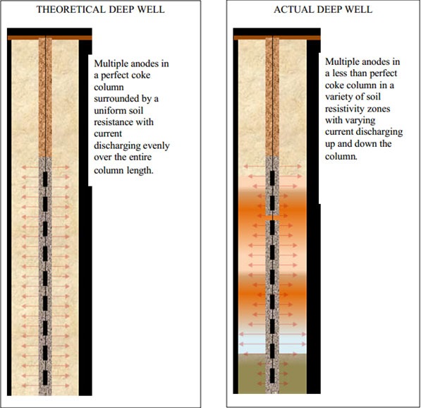
Many factors affect deep well anode performance. The theoretical model of a deep well, based on Dwight’s Equation, is of a single vertical rod in a homogeneous soil environment. In reality,a conventional discreet anode deep well consists of multiple anodes spaced in a vertical hole,surrounded by a less than perfect coke column that runs through varying soil conditions. The diagrams that follow show the vast difference between the theoretical construct that is Dwight’s equation and the actual operation.
Current Distribution – One important operational issue is current distribution. Ideally,each anode in the groundbed would operate at a similar output. For conventional graphite and high silicon cast iron anodes, which have relatively high consumption rates, uneven current discharge puts stress on some anodes which results in their premature depletion. This is a common problem and as the groundbed ages, more and more anodes become depleted and the groundbed performance can become quite irregular requiring frequent increases in voltage applied to produce the desired output.
Anode location is a factor in the uneven discharge in that the anodes with shorter leads located at the top of the groundbed have more applied voltage than the anodes at the bottom because of DC voltage drop through the anode cables – this is particularly true if the anode cables are undersized. If this were the only factor, however, then the anode output would decrease consistently as you move down the deep well.
Another factor impacting current distribution between discreet anodes is the mutual anode interference effect that occurs and inhibits current from traveling up and down the coke column. Each anode creates a voltage gradient which affects neighboring anodes.
Soil strata also affect individual anode output. Regardless of what happens inside the coke column, current discharging from the groundbed will be distributed outward based in large part on the soil resistivity profile surrounding the coke column. That is to say that the current will flow more readily into low resistivity zones and less readily into higher resistivity zones. With a properly installed coke column, there will be a low resistance path not only from the anode to the coke column to the soil interface, but also allow resistance path up and down the coke column. The goal is for the current from anodes in higher resistivity soils to be able to travel up or down the column and discharge current in low resistivity soils. Thus, with a low resistance coke column, each anode should have similar outputs regardless of what the immediate soil strata might be at that anode’s elevation.
Differential Anode Consumption – The effect of poor current distribution between anodes results in differential anode consumption. As anodes are consumed, the performance of the groundbed changes and the overall groundbed resistance increases. Over time, frequent upward adjustments to the voltage output on the rectifier are needed to achieve necessary current output. Eventually the groundbed cannot continue to meet the system’s requirements and must be replaced. Note also, that as the remaining anodes are pushed harder the localized current density increases and chlorine gas generation also increases – in the absence of proper venting this too can lead to premature failure.
Drying out of Groundbed– As part of the reaction occurring at the anode, water is hydrolyzed. As with chlorine generation, the quantity of water being reacted is a function of current density. In most soil environments, normal capillary diffusion replenishes the water being reacted. In some arid environments, however, there is not sufficient soil moisture to replenish the water being reacted, which can lead to drying out of the soil around the groundbed. In some cases watering systems are installed to periodically inject water either through a dedicated watering line or through the vent pipe.
MATCOR’S Durammo™ Deep Anode System Performance
Unlike conventional deep well anode systems, MATCOR’s Durammo® Deep Anode System utilizes a single continuous wire anode. The anode system has two Kynar cable leads: one connected to the top of the anode assembly and the other connected to the bottom of the anode assembly. Every ten feet there is a jumper wire creating a series/parallel arrangement to minimize voltage drop and provide electrical redundancy.
This anode arrangement offers several critical performance advantages over conventional discreet anode systems:
1. Enhanced Current Distribution– The single continuous anode means lower current discharge is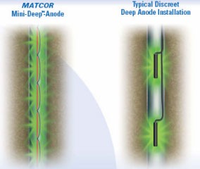 more evenly distributed up and down the coke column.
2. Eliminates Mutual Anode Interference –Mutual anode interference is eliminated,since there is a single anode.
3. Consistent Anode Wear – The MATCOR Durammo® Deep Anode System allows more even anode wear providing a more stable groundbed performance over time.
4. Dwight’s Model Preserved – Groundbed resistivity more closely approximates Dwight’s model because the actual anode length is the entire length of the active area.
5. Longevity – MATCOR’s system has a longer operating life because of the use of MMO anode and the reduced groundbed stress caused by multiple individual anodes all operating independently and at different outputs.
NOTE: The Durammo® Deep Anode System was previously marketed as the Mini-Deep™ Anode System.
Contact a Corrosion Expert


